Line symbols can be created in the Line Symbol Editor. A line symbol is composed of a number of child lines. A desirable line symbol can be created through child lines of different forms and styles. Therefore the basic element of a line symbol is a child line. The figure below illustrates an example of how child lines constitute a line.
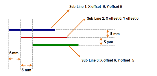
In the example in the figure below, a line symbol is to be made out of two child lines: child line 1 and child line 2. Both of the child lines are short dashes. According to the requirements, the line symbol is created by applying horizontal and vertical offsets to the child lines and setting the styles and widths of the child lines. The Line Symbol Editor provides a variety of types of child lines, based on which you can construct desirable line symbols by modifying the styles and formats.
Child Line Types
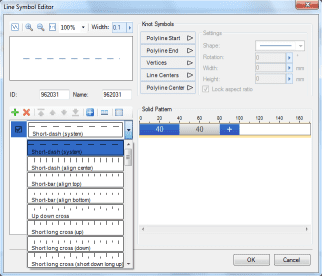
The creation of a line symbol in the Line Symbol Editor is based on child lines, and the editor provides a variety of child line types. As shown in the following figure, once a child line is added in the Line Symbol Editor, its type can be selected. The types shown in the drop-down list are basic child line types provided in the editor.
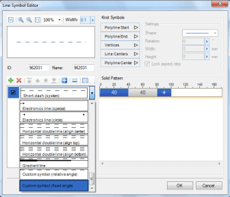
In addition, a child line can also be composed of specific symbols. In the figure below, the child line is a symbol child line, i.e., a child line composed of symbols. The distribution of the symbols in the child line, such as the intervals between the symbols, can be adjusted by setting the solid pattern of the child line (for more information about the solid pattern of a child line, please see the related content in later section). To set the type of a child line to symbol child line, the Custom Symbol option must be selected from the child line type list, as shown in the right figure above.
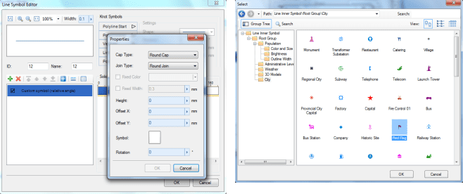
Once the child line type is set to the symbol type, the next step is to specify the symbol that constitutes the child line, and to adjust the child line’s solid pattern.
Select (Click the button identified in the figure to open the Select dialog box and select the symbol for creating the child line)
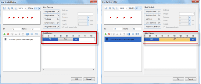
Set the solid pattern of the symbol child line (Compare two solid pattern settings)
Solid Pattern for Child Lines
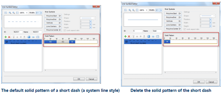
The solid pattern of a child line is used to determine which parts of this child line are filled with symbols and which parts are blank. Through the solid pattern, child lines like short dashes can be created. For example, the left figure below demonstrates a short-dashed child line (a system line style) whose solid pattern is circled in the figure. The blue block represents a solid part and the value in the color block represents the corresponding length; the grey block represents a non-solid part and the value in this color block represents the corresponding length.
In the right figure below, the solid pattern setting of the short dash is deleted, and the child line becomes a solid line.
So how to apply a solid pattern to a child line in order to change its visual effect? The following content provides a detailed explanation about that. Since there are different types of child lines, the same solid pattern applying to different types may produce different effects. The ways to interpret the effect of applying a solid pattern on child lines are described below.
Short-dash Types
When a child line is added and its type is set to the short-dash type (a system line style), the short-dash line has a default solid pattern. If this pattern is deleted, the child line will become a solid line. Thus a solid line can be considered as the basic element constituting a short-dash line, and a short-dash line is created by setting a solid pattern. Therefore, the effect of a solid pattern will be explained based on solid line elements.
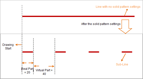
The child line in the figure below is a solid line. Suppose the solid pattern is set as: the value of the solid part is 20, and that of the non-solid part is 40. Once the setting is done, the child line will be drawn as follows:
- Draw a short solid line with the length of 20 units from the start point, given that the solid part is set to 20;
- Next, leave the child line blank within the next 40 units. The blank part is the predefined 40-unit long non-solid part;
- Then repeat the previous two steps.
Summarization of the solid pattern for this child line type: Draw content in the solid parts of the child line and leave the non-solid parts blank. The solid parts and the non-solid parts have predefined lengths. And the length unit is 0.1 mm.
In the Line Symbol Editor, the above solid pattern drawing method applies to the following child line types: double parallel lines (center aligned), double parallel lines (top aligned), and double parallel lines (bottom aligned).
Short-bar Types
This child line type is called Short-bar. In the example in the figure below, suppose the solid pattern is set as: the value of the solid part is 20, and that of the non-solid part is 40. Once the setting is done, a child line of the short-bar type will be drawn as follows:
- Draw a short bar at the position 20 units (solid part = 20) away from the start point of the child line;
- Next, draw a short bar at the position 40 units (non-solid part = 40) away from the short bar drawn in the previous step;
- Next, another short bar is drawn at the position 20 units (solid part = 20) away from the short bar drawn in the previous step. Continue this process till the solid pattern of a short-bar child line is completed.
In the Line Symbol Editor, the above solid pattern drawing method applies to the following child line types: short-long cross, short-bar (center aligned), short-bar (top aligned), and double parallel lines (bottom aligned).
Short-long Cross Types
This child line type is called Short-long Cross, i.e., a child line of this type is composed of alternating long bar and short bar elements. In the example in the figure below, suppose the solid pattern is set as: the value of the solid part is 20, and that of the non-solid part is 40. Once the setting is done, a child line of the short-long cross type will be drawn as follows:
- Draw a long bar at the position 20 units (solid part = 20) away from the start point of the child line;
- Next, draw a short bar at the position 40 units (non-solid part = 40) away from the bar drawn in the previous step;
- Next, another long bar is drawn at the position 20 units (solid part = 20) away from the bar drawn in the previous step. Continue this process and repeat step 2 and stop 3 till the solid pattern of a child line of the long-short cross type is completed.
In the Line Symbol Editor, the above solid pattern drawing method applies to the following child line types: short-long cross (upward), short-long cross (downward), short-long cross (long at top and short at bottom), and short-long cross (short at top and long at bottom).
Slash Types
This child line type is called Slash, i.e., a child line of this type is formed by slashes with certain tilt angles. In the example in the figure below, suppose the solid pattern is set as: the value of the solid part is 40, and that of the non-solid part is 80. Once the setting is done, a child line of the slash type will be drawn as follows:
- Draw a slash at the start point of the child line. The start point of the slash is where the drawing starts, and the end point of the slash is at the position 40 units (solid part = 40) away from the start point;
- Next, no content is drawn within 80 units (non-solid part = 80) from the end point of slash drawn in the previous step. In other words, the blank part is a predefined non-solid part with the length of 80;
- Next, another slash is drawn. The start point of this slash is the end point of the drawing in the previous step, and the end point of this slash is at the position 40 units (solid part = 40) away from the start point of this slash. Continue this process and repeat step 2 and step 3 till the solid pattern of a child line of the slash type is completed.
In the Line Symbol Editor, the above solid pattern drawing method applies to the following child line types: slash (/), and slash (\).
Slash (up down cross) Types
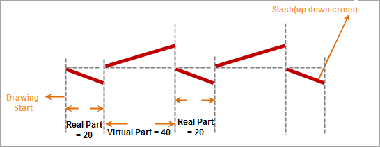
This child line type is called Slash (up down cross), i.e., a child line of this type is formed by alternating slashes with different tilt directions. In the example in the figure below, suppose the solid pattern is set as: the value of the solid part is 40, and that of the non-solid part is 80. Once the setting is done, a child line of the slash (up down cross) type will be drawn as follows:
- Draw a slash at the start point of the child line. The start point of the slash is where the drawing starts, and the end point of the slash is at the position 40 units (solid part = 40) away from the start point;
- Next, another slash is drawn. The start point of this slash is the end point of the drawing in the previous step, and the end point of this slash is at the position 80 units (non-solid part = 80) away from the start point of this slash.
- Next, another slash is drawn. The start point of this slash is the end point of the drawing in the previous step, and the end point of this slash is at the position 40 units (solid part = 40) away from the start point of this slash. Continue this process and repeat step 2 and step 3 till the solid pattern of a child line of the slash (up down cross) type is completed.
In the Line Symbol Editor, the above solid pattern drawing method applies to the following child line type: slash (up down cross).
Symbol Types
This child line type is called Symbol, i.e., a child line of this type is formed by specific symbol elements. In the example in the figure below, suppose the solid pattern is set as: the value of the solid part is 20, and that of the non-solid part is 40. Once the setting is done, a child line of the symbol type will be drawn as follows:
- A symbol is drawn at the position 20 units (solid part = 20) away from the start point for drawing the child line;
- Next, no content is drawn within 40 units (non-solid part = 40) from the symbol element drawn in the previous step. In other words, the blank part is the predefined non-solid part with the length of 80;
- Next, another symbol element is drawn at the position 20 units (solid part = 20) away from the end point of the drawing in the previous step. Continue this process and repeat step 2 and step 3 till the solid pattern of a child line of the symbol type is completed.
In the Line Symbol Editor, the above solid pattern drawing method applies to the following child line types: cross symbol (upward), cross symbol (downward), custom symbol (relative angle), and custom symbol (fixed angle).
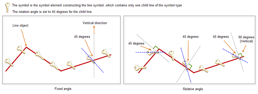
The figure below illustrates the difference between the Custom Symbol (relative angle) type and the Custom Symbol (fixed angle) type. Both of them are the Symbol type. The difference is:
- Custom Symbol (fixed angle): After a rotation angle is assigned to the symbols constituting a child line, the rotation angles of all the symbols in the child line must remain the same. Starting from the vertical direction, which has an angle of 0 degree, the degree value increases as the angle rotates anti-clockwise. Furthermore, when symbolizing a line object, no matter the object is a straight line or a polyline, the symbols in the child line always have the same rotation angle.
- Custom Symbol (relative angle): After a rotation angle is assigned to the symbols constituting a child line, the rotation angles of the symbols in the child line may not be all the same. For example, when symbolizing a polyline object, the rotation angle of a symbol, relative to the vertical direction which represents 0 degree, may change with the direction of the corresponding line segment. In this case, the positive direction perpendicular to line segment is taken as the starting direction whose angle is 0 degree, and the angle increases as it rotates anti-clockwise. When symbolizing a curve, the positive direction perpendicular to the tangent line of the curve is taken as the starting direction whose angle is 0 degree, and the angle increases as it rotates anti-clockwise.
In the following figure, the red polyline is the line object to be symbolized. To illustrate the difference between the Custom Symbol (relative angle) type and the Custom Symbol (fixed angle) type, the original line object is kept in the figures after it is symbolized with the line symbols.
Child Line Offsets
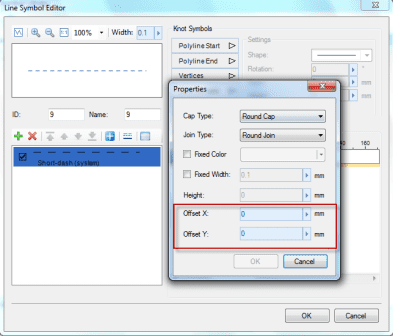
In the Line Symbol Editor, the default offsets of a newly created child are: horizontal offset = 0; vertical offset = 0; offset units: millimeters. You can control the relative positions between the child lines through setting their offsets.
Knot Symbols for Child Lines
Adding knot symbols on a child line is the process of adding specific symbols at special positions of a child line. The special positions where a knot symbol can be added include: the start point of a child line, the end point of a child line, the vertices of the child line, the centers of line segments, and the center of the entire polyline. The following content explains the effects of adding knot symbols on a child line through with illustrations.
- Polyline Start
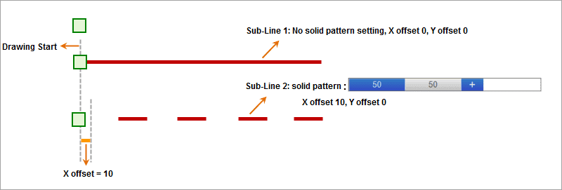
The figure below shows the effect of adding a knot symbol at the start point of a child line, i.e., adding a specific symbol at the point where the drawing of a child line starts. Two child lines, with different types, solid pattern modes, and styles, are used in the example to show the effects.
- Polyline End
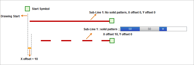
The figure below shows the effect of adding a knot symbol at the end point of a child line, i.e., adding a specific symbol at the point where the drawing of a child line ends. Two child lines, with different types, solid pattern modes, and styles, are used in the example to show the effects.
- Vertices
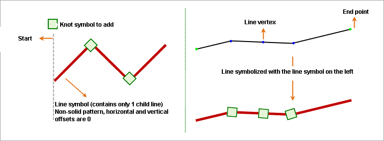
Adding knot symbols at the vertices of a child line has a more appreciable effect when symbolizing a line object. If knot symbols are added at the vertices of a child line of a line symbol, when using this line symbol to symbolize a line object, the specified knot symbol will be added to every vertex (except the two endpoints) of the line object. The following figure shows the effect of adding knot symbols at the vertices of a child line. The effect can be previewed in the Line Symbol Editor only when the Polyline mode is selected. The effect of using the child line to symbolize a polyline is also shown in the figure below.
- Line Centers
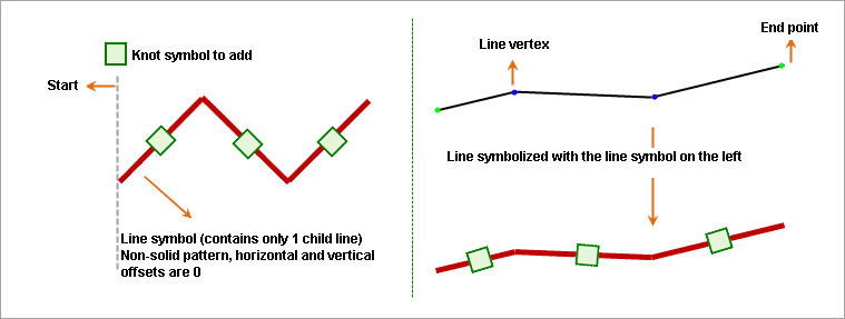
Adding knot symbols at the centers of the line segments of a child line has a more appreciable effect when symbolizing a line object. If knot symbols are added at the centers of the line segments of a child line of a line symbol, when using this line symbol to symbolize a line object, the specified knot symbol will be added to the center of the line segment connecting each two adjacent nodes of the line object. The following figure shows the effect of symbolizing a polyline object with a child line for which knot symbols are added at the centers of the line segments.
- Polyline Center
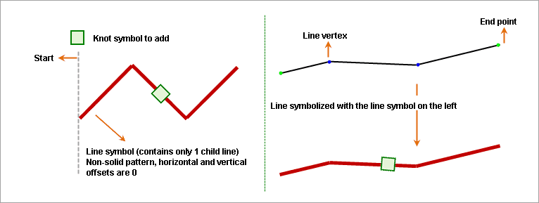
Adding a knot symbol at the center of a polyline has a more appreciable effect when symbolizing a line object. If a knot symbol is added at the center of the polyline of a child line of a line symbol, when using this line symbol to symbolize a line object, the center of this line object is first calculated, and then the specified knot symbol is added to that point. The following figure shows the effect of symbolizing a polyline object with a child line for which a knot symbol is added at the center of the polyline.

