Creating a section child line needs the following steps:
- Create a new section child line;
- Create the section for the section child line;
- Adjust the position of the section child line;
- Set the color or texture of the section.
Create Section Child Lines
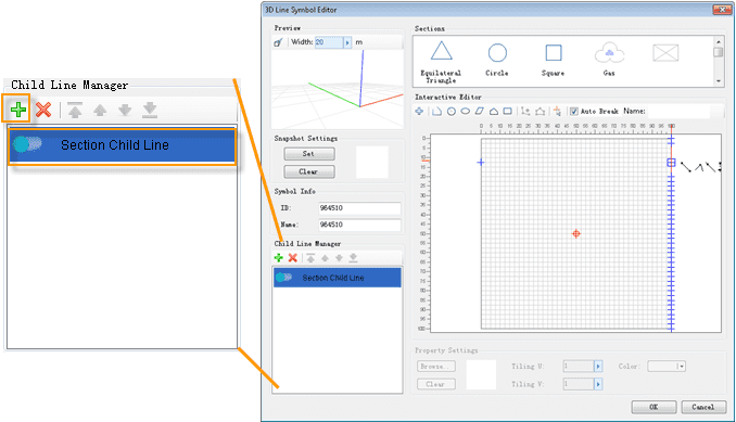
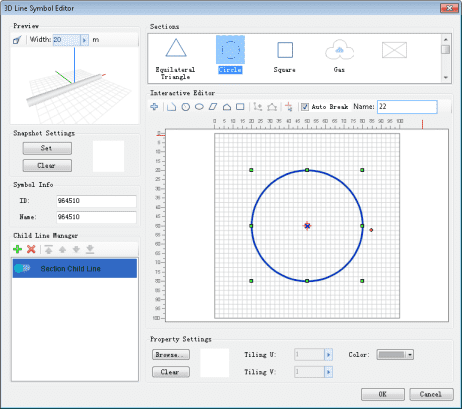
As shown in the figure below, once the 3D Line Symbol Editor is opened, a new section child line is created in the child line list by default. You can also click the Add button on the toolbar of Child Line Manager to add a child line, which would also be a section child line by default; if you want to change a model child line to a section child line, double click on the model child line, and select Section Child Line in the pop-up drop-down list.
Construct Sections
There are three methods to construct the section of a section child line:
- Draw: Draw a section in the drawing area of the Interactive Editing area;
- Import a 2D vector marker symbol: Import a 2D vector marker symbol and adopt it as the section of the section child line;
- Select a section used recently: Select a section from the recent section list.
Draw Sections
In the Interactive Editing area in the 3D Line Symbol Editor, as shown in the figure below, the interactive editing toolbar offers a series of section drawing and editing tools. These tools can help you draw needed sections quickly and easily. Further descriptions are listed below.
- Drawing Tools: The basic drawing tools for drawing sections. The usage is the same as that of the drawing tools in Marker Symbol Editor, please refer to the “How to use toolbar buttons to draw strokes” section in Drawing Strokes for the Marker Symbol.
- Add Node and Edit Nodes: To add, move, or delete nodes of the drawn section shape. Basic Steps:
- Add Node: Select the shape on which a node is to be added (note that only one shape can be selected for this operation), and click the Add Node button. Now all the nodes of the selected shape should be shown. Click at the target position on the shape to add a node there.
- Edit Nodes: Move or delete one or more nodes on the section shape. Select the shape for the operation, and click the Edit Nodes button. Now all the nodes of the selected shape should be shown. Select a node first, hold down the left mouse button, and move the mouse to move this node; select a node, or select multiple nodes by pressing down the Ctrl key or Shift key, and then press the Delete key to delete the selected node(s).
- Origin: the icon in the editing area is the intersection of the X , Y, and Z axes. It represents a point on the Earth surface in the real world. When changing the position of the origin, the change in the relative position between the corresponding 3D line and the intersection of the three axes can be seen in real-time in the preview window. Click the Set Origin button above the editing area and then click at the target origin position in the editing area to change the position of the origin point.
- Auto Split: If this check box is checked, the drawn shape will be automatically split at its nodes. Note that this does not apply to a Circle or an Ellipse. If this option is not checked, the drawn shape will not be split and will remain intact.
- Set Section Name: In the text box behind “Name: ”, input or edit the name of the section. In the recent section list, a name will be shown under each section to differentiate the sections.
Import 2D Vector Marker Symbol
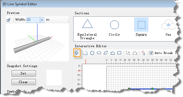
- Click the Add button above the recent section list area as shown in the figure below. A Select dialog box pops up;
- The pop-up Select dialog box shows the symbol library corresponding to the current workspace, in a symbol selector. Select the 2D vector marker symbol to be imported from the symbol list and click the OK button. Now the selected symbol should be added to the current section child line in the 3D Line Symbol Editor.
Since the Select dialog box shows the symbol library corresponding to the symbol library file in a symbol selector, operations similar to those in the Symbol Library Selector can be performed here. You can open another symbol library file through the function on the File menu in the Select dialog box, and select a 2D vector marker symbols to import.
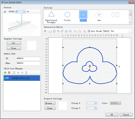
- After a 2D vector marker symbol is imported, as shown in the figure below, it is shown in the recent section list and is added in the current section child line. Note that once a 2D vector marker symbol is imported, its anchor point position will serve as the origin of the editing area.
Select Recently Used Sections
The recent section list in the upper right part of the 3D Line Symbol Editor lists all the sections used in the 3D line symbols in the current workspace, as well as the sections that were used during making the current symbol. In other words, every time a section is drawn or imported, it will be added to the recent section list.
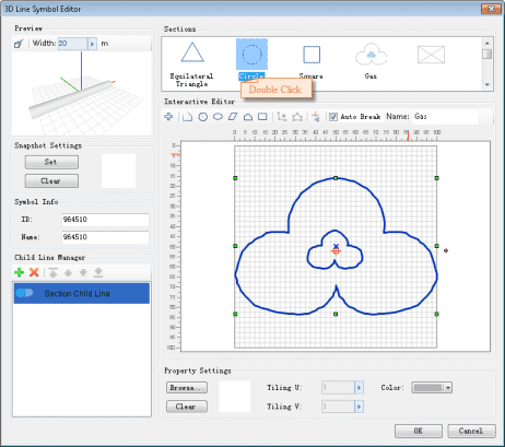
In the recent section list, double click any section shape to add this section to the section drawing area. If the section shape already exists in the section editing area, a prompting box will pop up to ask you whether to keep the existing section shape in the section drawing area. If Yes is clicked, the original section shape will be reserved and the newly selected section shape will also be added; if No is chosen, the existing section will be cleared from the section drawing area, and then the selected section shape will be added.
Adjust Section Child Line Position
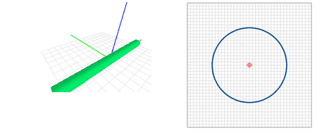
The relationship between the coordinate system of the editing area and that of the preview window is illustrated in the figure below:
The origin corresponds to the intersection of the X, Y, and Z axes. The plane formed by the X and Y axes corresponds to the horizontal surface of the Earth, and the Z axis is perpendicular to the horizontal surface; the horizontal direction of the editing area corresponds to direction of the X axis, which means that when a section is located to the left of the origin, the corresponding 3D line is located to the right of the X axis; the vertical direction of the editing area corresponds to the direction of the Z axis, which means that when a section is located above the origin, the corresponding 3D line is located above the plane formed by the X and Y axes.
Knowing the relationship between the coordinate system of the editing area and that of the preview area should enable you to adjust the position of a section as needed more quickly.
The steps to adjusting the position of a section are: Drag the mouse to select the entire section, hold down the left mouse button and move the mouse. Then release the mouse button at the target location to move the section to that position. Also, instead of the entire section, section parts can be selected in order to adjust the positions of certain parts of the section.
Set Color or Texture
Set Section Color
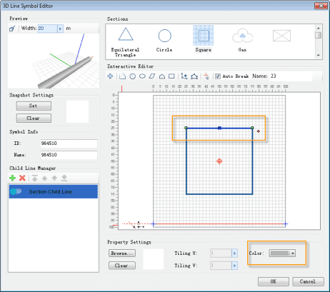
Select a section, or one or more lines of a section, and click the arrow on the right of the Line Color drop-down box. Select one color in the pop-up color list to set the color of the selected section. In the example in the figure below, a drop shadow effect can be seen in the preview window after a color is applied to the 3D line.
Set Mapping Texture
- Select a section, or one or more lines of a section;
- Click the Browse button in the texture setting area. In the pop-up Select Image dialog box, select the image that serves as the texture and click the OK button;
- Set the number of repetition of the image. The number of repetition of an image is the number of times the image is tiled on the surface of a 3D line. There are two types: Tiling U (in the X axis direction) and Tiling V (in the Y axis direction).
