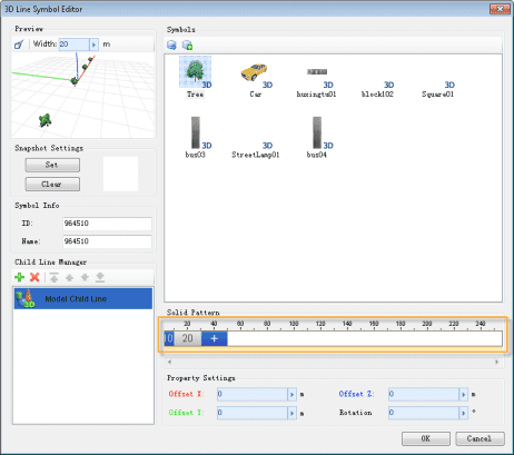
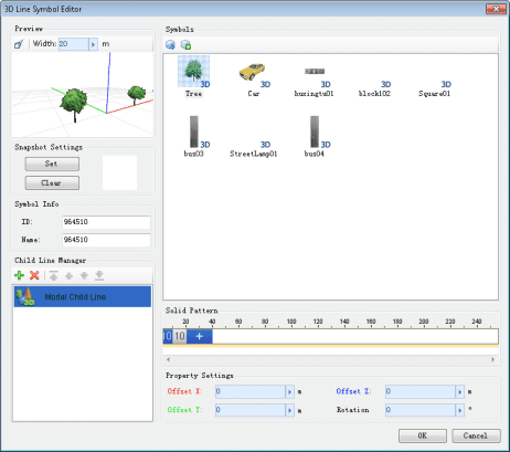
Creating a model child line needs the following steps:
- Create a new model child line;
- Select the 3D model constituting the child model line;
- Set the properties of the model child line, such as model interval and the rotation angles.
- Set the offset of model child line.
Create Model Child Lines
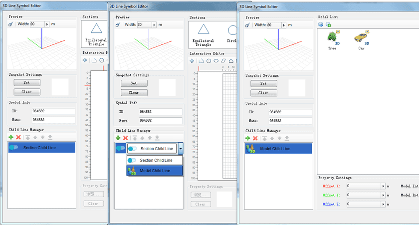
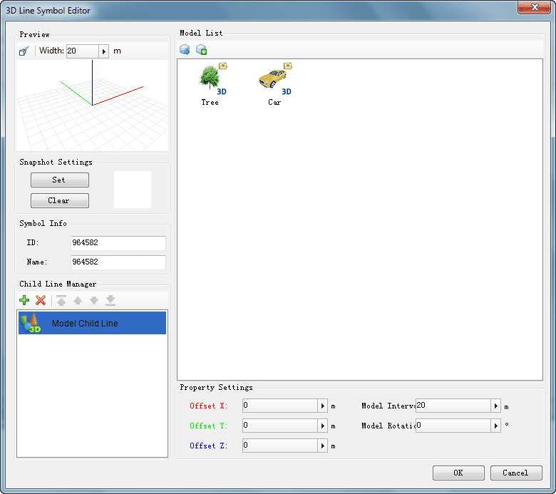
Once the 3D Line Symbol Editor is opened, a new section child line is created in the child line list by default. Now double click on the child line and the status of the child line will change to a drop-down list box as shown in the middle figure below. Click the drop-down button. The child line type list then pops up. Choose Model Child Line here to complete creating the model child line.
In addition, a new model child line can also be added through the following steps:
- Click the Add button in the toolbar of Child Line Manager to add a child line;
- Double click on the newly added child line. The status of the child line changes to a drop-down list box. Click the drop-down button on the right and choose Model Child Line in the pop-up child line type list.
Select the Model
There are two ways to obtain the 3D model for creating a model child line: One is to select a 3D marker symbol stored in a marker symbol library and adopt the marker symbol as the 3D model constituting the child line; the other way is to import a 3D model file (*.sgm or *.3ds) and adopt the 3D model in the 3D model file as the 3D model constituting the child line.
The steps of the two methods to select a 3D model for creating a model child line are described in details below.
Import 3D Marker Symbol
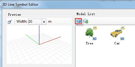
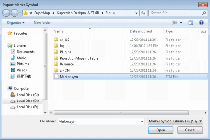
- Click the Import 3D Symbol button. The Import Marker symbol dialog box pops up, as shown in the figure below;
- In the Import Marker Symbol dialog box, select the marker symbol library file that contains the target 3D marker symbol and open it;
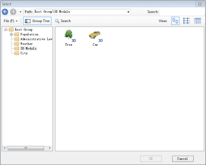
- The Select dialog box pops up. This dialog box shows the symbol library corresponding to the opened marker symbol library file in a symbol selector. From the symbol list, select the 3D marker symbol to be imported.
Since the Select dialog box shows the symbol library corresponding to the symbol library file in a symbol selector, operations similar to those in the Symbol Library Selector can be performed here. You can open another symbol library file through the function on the File menu in the Select dialog box, and select a 3D marker symbols to import.
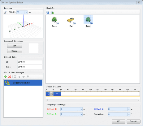
- After a 3D marker symbol is imported, as shown in the figure below, it shows up in the model list. Select a 3D model from the list to make the current model child line. The created model child line is then displayed in the preview area.
Import 3D Model
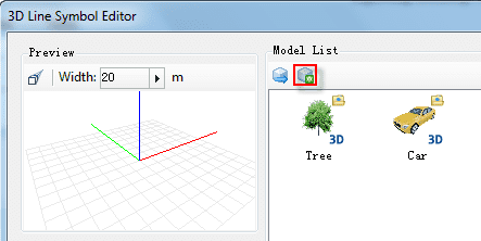
- Click the Import 3D Model button as shown in the figure below. An Open dialog box pops up;
- In the Open dialog box, select the 3D model (*.sgm or *.3ds files) to be imported and click on Open;
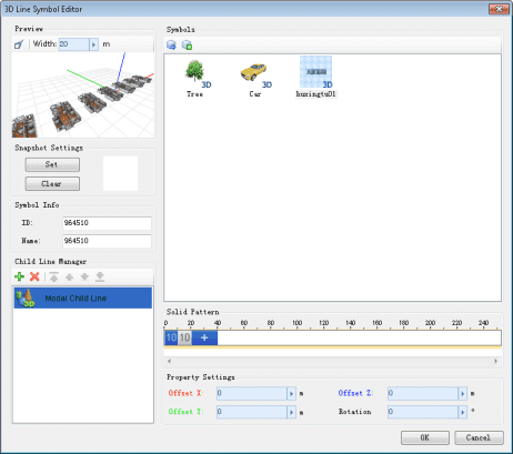
- After a 3D marker symbol is imported, as shown in the figure below, it shows up in the model list. Select a 3D model from the list to make the current model child line. The created model child line is then displayed in the preview area.
In addition, the rotation angle of the models in a model child line can be set through the Rotation property in the Child Line Property Setting area. To set the value, you can directly input a value in the Rotation box, or click the arrow on the right and adjust the position of the pop-up slider bar, or click the Zoom In or Zoom Out button.
Set properties for Model Child Lines
The model interval of a model child line is for controlling the interval between each two adjacent 3D models that are arranged in a line to form a model child line.
The model angle of a model child line is for controlling the rotation angle of 3D model in in the horizontal direction.
Set Offsets for Model Child Lines
The Offset X, Offset Y, and Offset Z in the Child Line Property Setting area are used to set the offsets of the model child line along the X, Y, and Z direction, respectively. The offset unit is meter. You can directly type a value in the box or move the slide bar that will show up by clicking the right arrow.
The preview area of the 3D Line Symbol Editor shows the axes of a 3D space. The axes are differentiated with three different colors. Also, the text for the Offset X, Offset Y, and Offset Z properties has the corresponding colors. In this way, the offset effects along the three axes can be easily differentiated. As shown in the figure below, the X axis is red, the Y axis is green, and the Z axis is blue.
