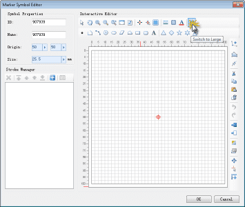
The Marker Symbol Editor provides tools such as ruler, background grid, and snapping function to assist with symbol creation and editing. You can also set these tools as needed to produce a custom symbol editing environment that suits your own requirements. These settings are referred to as symbol editor environment settings. The following content describes how to set the symbol editor environment.
Valid Bounds of Editing Area
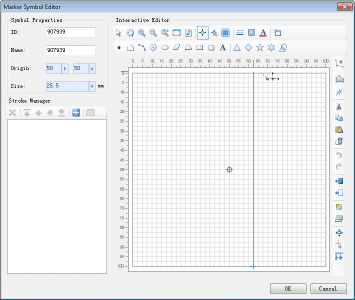
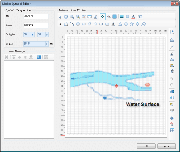
The valid bounds of the editing area are the bounds marked by the ruler. The objects drawn outside of the bounds will be discarded. As shown in the figure below, the bounds defined by the grid represent the valid bounds of the editing area. Only the objects drawn in the valid bounds are going to be used to create the marker symbol.
Symbol Size and Display Size
The valid bounds of the editing area correspond to the valid bounds of the resulted marker symbol, as shown in the figure below. In real applications, the display size of a marker symbol on a map is determined by setting the size of the marker symbol. There are two types of sizes for marker symbols: marker size and display size:
- The display size of a marker symbol is the size of the minimum bounding box that contains all the geometric objects of the marker symbol.
- The marker size refers to the size of the valid bounds of the marker symbol.
- When creating a marker symbol in the editing area, the ratio of the height/width of the minimum bounding box containing all the drawn geometric objects (those located within the valid bounds) to the height/width of the valid bounds of the editing area equals the ratio of the height/width the display size to the height/width of the marker size. This means that once the marker size of the symbol is set, the display size of the symbol can be calculated based on the ratio, and vice versa.
- When creating a marker symbol in the editing area, the relative position between the minimum bounding box containing all the drawn geometric objects (those located within the valid bounds) and the valid bounds of the editing area determines the relative position between the minimum bounding box and the valid bounds of the symbol. This means that the relative position between the object content and the valid bounds of the symbol does not change when the symbol size changes.
If the minimum bounding box containing all the geometric objects of the marker symbol overlaps with the valid bounds of the symbol, the marker size equals to the display size. In most cases, the creator and the user of a symbol are not the same person, and the user does not know the ratio of the height/width of the minimum bounding box containing all the symbols to that of the valid bounds. In this case, the user can directly control the display size of the symbol by setting it.
When setting the symbol style, suppose the marker size of the marker symbol in the above figure is set to 50. It is known that the ratio of the height of the valid bounds to that of the minimum bounding box containing all the geometric objects is 5:3, and so is the ratio of the width of the former to that of the latter. In this case, the display size of the symbol can be calculated and the result is 30; if the display size of the symbol is set to 60, the marker size can be calculated and the result is 100.
In the following figure, three marker symbols are first created in the Marker Symbol Editor, and then the marker sizes and display sizes of the three marker symbols are set. The result of the setting further explains the relationship and difference between the marker size and the display size.
Background Settings for Editing Area
The background of the editing area is a grid by default. The grid is aligned with the ruler lines, and can be used for accurate positioning. Furthermore, a picture can also be adopted as the background of the editing area so that symbols can be drawn through vectorization.
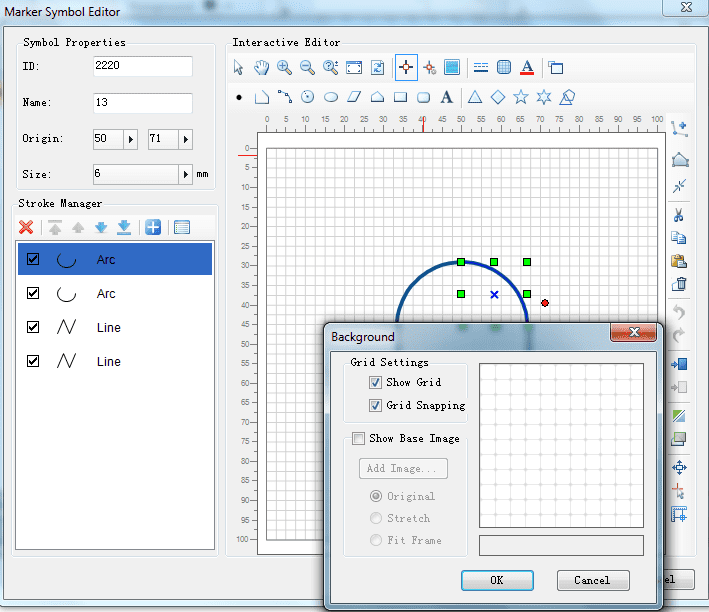
- In the Marker Symbol Editor, click the Background button to open the Background dialog box. The background style of the editing area can be set here.
- The Show Grid check box controls whether to show the background grid in the editing area: Check it to show the grid; uncheck it to make the grid invisible.
- Checking the Show Base Image check box can add a grid image to serve as the background of the editing area. If the check box is checked, related functions in the area are activated for further setting the background image added in the editing area. Also, previewing functions are provided on the right to preview the effect of the background setting in real-time. Specifically, these functions include:
Add Image: Click the Add Image button to open the Open dialog box. Find the needed image and open it to add it in the editing area and make it the background.
Original: If Original is selected, the image file will be added in the editing area with its original size.
Stretch: If Stretch is selected, when the original image is added in the editing area, it is stretched to fill the entire valid bounds of the editing area.
Fit Frame: If Fit Frame is selected, when the original image is added in the editing area, it is properly stretched so that its height or width fit the height or width of the valid bounds of the editing area.
- Once the background is set, click the OK button in the Background dialog box to apply the settings and close the dialog box.; or click Cancel to cancel the settings.
Ruler of Editing Area
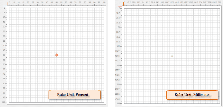
The ruler in the editing area marks the area’s valid bounds and also facilitates measurements during a symbol editing process. There are two types of units for ruler values: 0.1 mm and percentage. The two can be switched to each other through Ruler Percent or Ruler Real button in the vertical toolbar. If the current ruler unit is percentage, the switch button in the vertical toolbar is Ruler Real, and a click on this button will switch the ruler unit to 0.1 mm while at the same time the button changes to Ruler Percent, and vice versa.
Snap Settings
When editing a symbol in the Marker Symbol Editor, the snap functions can be used to handle the relationships between the strokes and the positions of mouse clicks. There are two types of snapping here: snapping strokes, and snapping background grid lines in the editing area.
- In the Marker Symbol Editor, click the Snap On/Off button to open or close the snapping function in the editing area to determine whether to snap necessary objects during editing.
- If the snapping function in the editing area is open, click the Background button to open the Background dialog box. The Snap Grid check box controls whether to snap background grid lines in the editing area: if it is checked, grid lines are snapped; otherwise, grid lines are not.
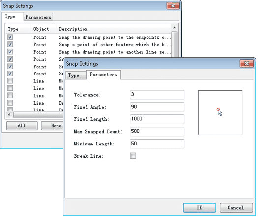
- In the Marker Symbol Editor, click the Snap Setting button to open the Snap Setting dialog box in which the snapping type and parameters can be set.
Full Extent Display of Editing Area
In the Marker Symbol Editor, click the Switch to Large button to display the editing area with full extent. To go back to the normal mode, click the ESC key or the Switch to Normal button, or click at any place in the black area in the full-extent display.
