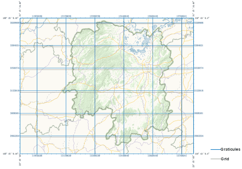
A geographic grid is a network which composes of evenly spaced horizontal lines and vertical lines to identify each location on a map. iDesktop provides two types: Graticules and Grid. Graticules are lines depicting longitude and latitude to denote geographic coordinates while a grid is used to identify projection coordinates of a map.
Except for the plane coordinate system which can not display graticules, you can use grids and graticules to display coordinate systems at the same time on the same map.
- Geographic coordinate system: supports both graticules and grids;
- Projection coordinate system: supports both graticules and grids;
- Plane coordinate system: supports only grids.
Application Scenarios
- According to cartographic specification and requirements in China, to produce an reasonable map, you should add grids, borders of each map, etc. on your map layout.
- When your map covering not only one UTM zone, you can use multiple geographical grids to identify the corresponding coordinate system on each UTM zone to make locations more accurate.
Create a Geographical Grid
SuperMap iDesktop allows you to create grids through templates or to customize them.
- Predefined template: you can create map grids by setting related parameters based on template styles.
Function Entrances
- Ribbon: Object Operations -> Drawing -> Grid.
- Layout Map Properties: Map Grid -> **Add icon button in the toolbar.
Parameter Settings:
- Grid Type: Specify which geographic grid you want.
- Coordinate: If you set Grid Type to Measure Grid, you can set Coordinate to a projection coordinate system. But if you set Grid type to Graticules, iDesktop will show you the geographic coordinate system of your map automatically.
- Horizontal Interval: The distance between two adjacent horizontal lines. For graticules, the unit of interval distance is degree while meter for a measure grid.
- Vertical Interval: The distance between two adjacent vertical lines. For graticules, the unit of interval distance is degree while meter for a measure grid.
- Column/Row: Based on the given horizontal and vertical intervals, iDesktop will work out the number of columns and rows of a grid. If you change the value of Column/Row, Horizontal/Vertical Interval will change together.
- Template File: In the Layout Map Properties panel, after expanding Map Grid, click on the Import icon. In the pop-up dialog box, browse to the template file (*.xml) you want and click Open to import it.
Manage Grids
- Map Grid Settings: click the Settings icon in the toolbar to open the Map Grid Settings dialog box where you can modify parameters on geographic grids.
- Grid Template: A template file can be imported to create a grid. Also you can export a grid as a template file.
- Move Up/Down: The display order of each grid can be adjusted.
- Delete: You can choose a grid from the list to remove it. Once the selected grid is removed, it cannot be recovered.
- Visibility: The icon in the grid list controls the visibility of each grid.
- Rename: Double click on the name of the grid you want to rename. And then you can edit it.
Grid Style
- Frame Style: Click on the grid style of each grid to open a dialog where you can change lines’ styles. About how to change line’s style, please refer to Line Symbol Style.
- Grid Type: Click on the Grid Type and then you can choose a line type from Solid Line, Crossline, and None.
- Grid Style: For the solid-line grid and the crossline grid, you can click on the dropdown button Grid Style to change the style, width, and color of the grid line.
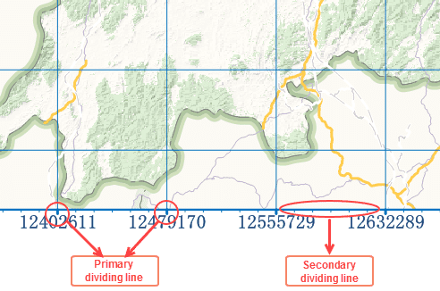
- Primary Dividing Line: A primary dividing line is a line which is located at the intersection between a grid line and a map border. Click the dropdown button beside Primary to change the primary dividing line’s style.
- Secondary Dividing Line: A secondary dividing line is a line showing on a map border between two adjacent primary dividing lines. According to the number of secondary lines between two primary dividing lines you specify (the value of Segment Line Number), iDesktop will divide evenly space between any two adjacent dividing lines. As the following example illustrates, the value of Segment Line Number is 5, hence iDesktop divide space between any two adjacent primary dividing lines into 6 parts to draw 5 secondary dividing lines. It is possible to make secondary invisible in the control of Secondary checkbox. Click the dropdown button beside Secondary to change the secondary dividing line’s style. Note: secondary dividing lines can work on a measure grid.
Label Style
Coordinates of a grid or graticules are labeled in two ways: Around Label and Corner Label.
- Around Label: Label the coordinate of each grid line after you checking the checkbox.
-
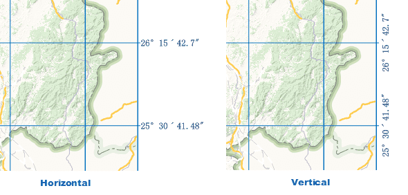
Horizontal Position: Adjust the position of each coordinate label of vertical grid line relative to the corresponding primary dividing line.
- Middle: The center of each label is in the same line as the center of the corresponding primary dividing line.
- Left: Each label is located at the left side of the corresponding primary dividing line.
- Right: Each label is located at the right side of the corresponding primary dividing line.
-
Vertical Position: Adjust the position of each coordinate label of horizontal grid line relative to the corresponding primary dividing line.
- Middle: The center of each label is in the same line as the center of the corresponding primary dividing line.
- Top: Each label is located above the corresponding primary dividing line.
- Bottom: Each label is located below the corresponding primary dividing line.
- Offset: The offset of each coordinate to map frame. Unit: 0.1mm.
- Show Vertically: controls whether to show coordinate label vertically. Displaying labels horizontally is by default.
- Visible: Controls visibilities of labels at the left, top, right, and bottom of the map frame.
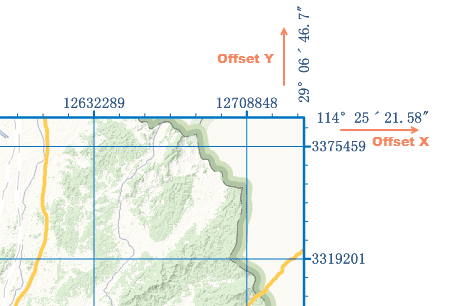
- Corner Label: Label the coordinate of each corner of a rectangle map frame.
- Offset X: The offset of each corner label to the map frame in the horizontal direction. Unit: 0.1mm.
- Offset Y: The offset of each corner label to the map frame in the vertical direction. Unit: 0.1mm.
-
Label Position: controls the position of each corner label relative to the extension line of the corresponding grid line.
- On Extension Line: the center of each coordinate label is located on the extension line of the corresponding grid line.
- Off Extension Line: the center of each coordinate label is located off the extension line of the corresponding grid line.
- The number of each coordinate: On a big-scale map, the coordinates shown by each grid line are the same at the first several digits. Therefore, to make each label more simple, you can specify how many digits (counting from the decimal point) to be shown. Note: It is not suggested to use the feature on graticules.
- Integer Count: Specifies the digits of integer part of each coordinate. For example: for 243547, if you set Integer Count to 4, the label will be 3547.
- Decimal Count: Specifies the digits of fractional part of each coordinate. For example: for 3698.1826, if you set Decimal Count to 2, the label will be 3698.18.
- Other Settings: You can set the font, size, color, and so on of text shown in each coordinate label. For more details on how to set these properties, please refer to Text Properties.


