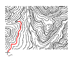
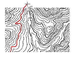
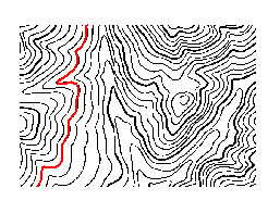
Semi-auto vectorization refers to vectorizing a raster base map through man- machine interaction. The main steps include track settings, auto-tracking lines, undoing lines, and auto-tracking polygons. Here, we take the vectorization of a contour map as an example to introduce how to use the feature.
1. Data Preparation
Import the image file you want to vectorize and georeference the image. Create a new line dataset or CAD dataset which is used to store vector contour lines. Place the raster dataset and the new line (CAD) dataset to the same map window.
2. Raster to Vector Settings
Set the line (CAD) dataset editable in Layer Manager. Click Object Operations > Raster to Vector group > Settings button to open the dialog box Raster to Vector where you can set parameters.
Select a raster layer. Set the background color and color tolerance, so that any color value (RGB) falls in this color tolerance will be treated as the raster base color. The default color tolerance value is 32. Then set the smooth factor (after filtering sawtooth, how many interpolation points can be inserted between the two points along a line) and the filter pixels (de- aliasing parameter). You can also use the default values. Finally, Set the base color white, in this case, iDesktop will not track the base color of the raster layer during vectorization.
- Raster Layer: Select the image layer which you want to vectorize as the base layer.
- Background: Set the base color white, in this case, iDesktop will not track the base color of the raster layer during vectorization.
- Color Tolerance : The degree of similarity of the raster base map. It will continue tracing when any component value of RGB is less then the tolerance. Its value range is from 0 to 255, and the default value is 32.
- Filter Pixels : Set the filter parameter, i.e., eliminates the vertical offset distance that the serration of the line object flutters with the grating method. The default value is 0.7. The greater the parameter, the more points it filters.
- Smoothness : The vectorization needs the smooth operation. The greater the smoothness, the smoother the boundary of the vector line/region.
- Auto Pan : If the Auto Pan check box is checked, the application will move the map automatically, i.e., the window will automatically move when the mouse clicks the border of the window during vectorization. If the Auto Pan check box is unchecked, the window has to be moved manually.
3. Semi-auto Tracking Lines
- Click Object Operations > Raster to Vector > Vectorize Line.
- Move the mouse to a line object and left-click on it to start drawing the line object. When the mouse meets a breakpoint or a crossing during vectorization, the operation will stop and you need to double-click the next point on the forward direction line of the breakpoint or crossing. Then the tracing will go on until it meets another breakpoint or crossing.

- Right-click when you meet an endpoint of a line segment to trace in a reverse direction from the start point. The vectorization stops when it reaches the other endpoint of the raster line.

- Right-click to end vectorizing. If the raster line is closed, it will be closed automatically during vectorization.

4. Undo Lines
The quality of the raster base map influences the result of vectorization. You can use the Undo Line command to undo the drawing of partial line segments, and then left-click to do this, or right-click to return to the current vectorizing state. If you finish vectorizing, the Undo Line button will turn gray and be unavailable.
If you undo on the U line, maybe you cannot go back to the status you want. In this case, we suggest you click at the corner and then undo line. Move the mouse pointer can undo your operations.
Vectorize Region
For semi-auto vectorization, some raster needs to be vectorized to regions, such as rivers, lakes, etc. The operations of vectorizing regions are similar to vectoring lines. Set the region layer editable, and set related vectorization parameters. Click the Object Operations tab, find the Vectorization group, and click the Vectorize Region button. Move your mouse to the map, click and draw the region on the layer. The cell within the tolerance can be vectorized. Right click to finish the vectorizing. The region can be adjusted by Object Edit.
Note
- During vectorization, you can use Zoom In (Zoom Out, etc.) to adjust the scale of the raster base map. Right-click to continue vectorizing.
- Click Esc or click the Vectorize Line button on the Raster to Vector group to cancel the current drawing.
- With Alt + Q shortcut keys, you can quickly and easily use the Vectorize Line function.