The Object Drawing group on the Object Operation tab allows you to draw point, line, surface, and so on Geometries in a Layout, basically in the same way that you draw Geometries in a Map. However, the drawing in the current layout does not support the drawing of input coordinates or Input Parameters. It also supports adding text and picture objects to the layout. When drawing objects, it supports setting snap, which improves the accuracy and efficiency of users in Object Editing.
Application can use the tools provided in the " Object Drawing" group to draw various types of points, lines, and Regions that can be directly created in Layout. A total of 20 types of Geometry that can be directly drawn are provided.
Point
On the Object Operation tab, the Object Drawing group organizes the tools for drawing point objects in Layout.
Click Object Drawing | |||
Button |
Explain |
Function and operation method |
Schematic diagram |
Draw points | Click the "Point" button to display the point cursor; click the left mouse button at the position to be drawn in Layout to draw a point object. Each left mouse click creates a point object, and a right mouse click ends the Point Object Drawing. |
Remarks
End Point Object Drawing has the following two methods:
- Right-click any nonpoint object in Layout.
- Click the button for Object Drawing in the Object Drawing group of the Object Operation tab again.
Line
On the Object Operation tab, in the Object Drawing group, you have organized the tools for Draw Line Objects in a Layout. Application provides several commonly used line objects that you can draw directly in a Layout.
Line Object Drawing | |||
Button |
Explain |
Function and operation method |
Schematic diagram |
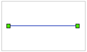
Draw a line | Click the Line button, and the line cursor appear ; Move the line cursor to the position where the line is created in Layout, and click the left mouse button to draw an endpoint of the line; move the cursor to the appropriate position and click the left mouse button again to complete the drawing of a line. | ||
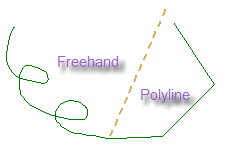
Draw a polyline | Click the Polyline button and the polyline cursor appear ; Move the polyline cursor to the position where the polyline is created in Layout, and click the left mouse button to draw the first node of the polyline; continue to move the cursor to the appropriate position and click the left mouse button again to draw the first edge of the polyline; continue to draw each node of the polyline in the same way, and finally click the right mouse button to complete the drawing of the polyline. | ||
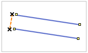
Draw parallel lines | Creates a parallel line with only two sub-objects. Click the Drop-down Button of the "Broken Line" button, select "Parallel Line" in the pop-up drop-down menu, and the parallel line cursor appears; click the left mouse button at the position where the parallel line is created to determine the starting position of the parallel line; Move the mouse and click the left mouse button again at the position where the width of the parallel line can be determined to determine the width of the parallel line; move the mouse to see that the width of the parallel line has been determined and its length changes with the movement of the mouse pointer. Click the left mouse button at the appropriate position to determine the length of the parallel line. The procedure for drawing additional segments of the parallel line thereafter is similar to that for drawing a polyline. Right-click to end the drawing of the parallel line. |
||
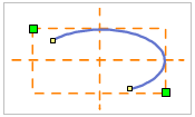
Draw an elliptical arc | Click the Arc button. The arc cursor appears. ; Move the arc cursor to the position where the arc was created (i.e. one of the diagonal positions of the arc Bounds), and click the left mouse button to determine the position of the arc; Move the mouse, and you can see that the size of the blue temporary ellipse changes with Move Stop by Mouse. In the place where the size of the ellipse is determined, click the left mouse button to determine the size of the ellipse; Move the mouse to see a small green square moving on the temporary ellipse with Move Stop by Mouse. Click the left mouse button at the starting position of the arc to determine the starting point of the arc; Move the mouse and click again at the end of the arc to determine the shape and size of the arc. | ||
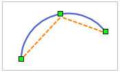
Draw a 3-point arc | Creates a three-point arc from three consecutive points. Click the Drop-down Button of the Arc button, and select Three-point Arc from the pop-up drop-down menu to display the three-point arc cursor . ; Click the left mouse button at the position where the three-point arc is created to determine the first point of the arc; click the left mouse button again at the appropriate position to determine the second point of the arc, move the mouse, and you can see that the size of the blue temporary circle changes with Move Stop by Mouse. Click the left mouse button again at the end of the three-point arc to finally determine the shape and size of the three-point arc. |
||
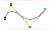
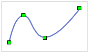
Draw B-spline curves | The curve is drawn by determining the first and last control points of the curve and the intermediate control points which are not on the curve, and the intermediate points of the curve are fitted according to the intermediate control points on the curve. Click the Drop-down Button of the Curve button, select B-Spline Curve "in the pop-up drop-down menu, and the B-spline curve cursor appears. ; in the place where the B-spline curve is created, click the left mouse button to determine the first control point of the curve; in the appropriate position, click the left mouse button again to determine the second control point of the curve; Move the mouse, and you can see that the blue temporary curve changes its smoothness with Move Stop by Mouse. Click the left mouse button again at the appropriate position to determine the other control points of the curve. |
||
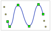
Draw a Bezier Curve | The direction of the curve is controlled by two Start Nodes and two End Nodes which are not on the curve, and the middle points of the curve are fitted by other control points on the curve. At least 6 control points are required to complete the drawing of a Bezier Curve. Click the Drop-down Button of the Curve button, select Bezier Curve "in the pop-up drop-down menu, and the Bezier Curve cursor appears. ; Click the left mouse button to determine the first control point of the curve; Click the left mouse button again at an appropriate position to determine the second control point of the curve, and a blue dotted line is formed between the two points; click the left mouse button continuously at the position where the curve is created, and you can see that an arc segment is formed between the two control points from the third control point, and finally click the right mouse button to end the drawing of the Bezier Curve. |
||
Draw the Cardinal curve | The curve is drawn by determining the control points on the curve, and the middle point of the curve is fitted according to all the control points. Click the Drop-down Button of the "Curve" button, select "Cardinal" in the pop-up drop-down menu, and the Cardinal curve cursor appears. ; Click the left mouse button to determine the first control point of the curve; click the left mouse button again at the appropriate position to determine the second control point of the curve, and you can see a blue dotted line between the two points; Move the mouse to see another blue dotted line drawn from the second control point, and click the left mouse button again at the appropriate position to determine the third control point of the curve, and create a Cardinal curve between the three control points; Move the mouse, and you can see that the blue temporary curve between the second and third control points changes its smoothness with Move Stop by Mouse. Click the left mouse button again at the appropriate position to determine the other control points of the curve. When you have drawn all the control points, right-click to end the operation. |
||
Draw a Free Curve | Click the Drop-down Button of the Curve button, select Free Curve "in the pop-up drop-down menu, and the Free Curve cursor will appear ; Move the cursor to the position where the Free Curve is created, click the left mouse button, press and hold the left mouse button, and move the mouse to draw a curve consistent with the cursor movement track in Layout; if you want to draw a polyline, you can release the left mouse button, move the mouse, and click the left mouse button at the next node of the polyline; When you finish drawing, right-click to end the operation. |
Remark
- When Draw Line Objects , support the shortcut key Ctrl + R reverse, the drawing direction will automatically jump to the other end of the line object, continue the drawing of the line object. The reverse drawing function can adjust the drawing direction at any time to improve the drawing efficiency of longer objects.
- End line Object Drawing has the following two methods:
- Right-click any nonlinear object in
- Layout. Click
- again the button corresponding to the line Object Drawing in the Geometry group on the Object Drawing tab.
Face
On the Object Operation tab, in the Object Drawing group, you are organized with tools for Draw Surface Objects in Layout. Application provides 10 types of face objects that you can draw directly in Layout.
Face Object Drawing | |||
Button |
Explain |
Method of operation |
Schematic diagram of operation steps |
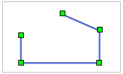
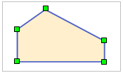
Draw Polygon | Click the Polygon button, and the polygon cursor appear ; Move the polygon cursor to the position where you want to create the polygon. Click the left mouse button to draw the first node of the polygon. Move the cursor to the appropriate position and click the left mouse button again to complete the drawing of the first sideline. Repeat the above steps; finally, click the right mouse button to end the Draw Polygon operation. The system will Autoconnect the first node and the last node to draw the last edge. | ||
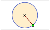
Draw a center circle | Creates a circle with a center point and radius. Click the Circle button to display the center circle cursor ; Click the left mouse button at the position where the circle is created to determine the center of the circle. Click the left mouse button again at the position where the shape and size of the circle are determined to complete the operation of the circle. |
||
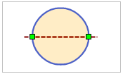
Draw a two-point circle | Creates a circle with a diameter defined by two points. Click the Drop-down Button of the "Circle" button, select "Two-point Circle" in the pop-up drop-down menu, and the oblique ellipse cursor will appear. ; Click the left mouse button at the position where the circle is created to determine one endpoint of the circle diameter. In the appropriate position, click the left mouse button again to determine the other endpoint of the circle diameter and the length of the circle diameter to create the circle object. |
||
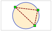
Draw a three-point circle | Create a circle by defining the circumference with three points. Click the "Circle" button, select "Three-point Circle" in the pop-up drop-down menu, and the three-point circle cursor will appear. ; At the location where the circle was created, click the left mouse button to determine the first point of the triangle inscribed in the circle. In the appropriate position, click the left mouse button again to determine the second point, thus determining one side of the inscribed triangle. You can see that the size of a temporary circle object changes with Move Stop by Mouse. Repeat the previous step to determine the last point and complete the operation of drawing a circle with three points. |
||
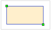
Draw Rectangle | Click the Rectangle button. The rectangle cursor appears. ; Move the rectangle cursor to the location where the rectangle was created. Click the left mouse button and move the mouse along the diagonal of the rectangle. You can see a blue rectangular box that changes in size and aspect ratio as you move the mouse. Click the left mouse button again at the appropriate position to determine the size of the rectangle and complete the Draw Rectangle operation. | ||
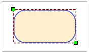
Draw a Rounded Rectangle | Click the Drop-down Button of the Rectangle button, select Rounded Rectangle "in the pop-up drop-down menu, and the Rounded Rectangle cursor will appear ; Move the Rounded Rectangle tool cursor to the location where the Rounded Rectangle was created, and click the left mouse button to locate the first node of the rectangle. Move the mouse, and you can see a blue rectangle changing in size and aspect ratio as you move the mouse. Click the left mouse button in the appropriate position to determine the size of the Rounded Rectangle. Move the cursor up and down at this point, and you can see that the four angular radians of the Rounded Rectangle change accordingly. Adjust to the appropriate radian and click the left mouse button to complete the Rounded Rectangle drawing operation. | ||
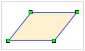
Draw the Paralle logram | Click the Drop-down Button of the Rectangle button, select Paralle logram "in the pop-up drop-down menu, and the Paralle logram cursor will appear ; Click the left mouse button at the place where the Parallelogram is created, move the mouse, and the length of a blue line changes with the size of Move Stop by Mouse. Click the left side of the mouse again to the appropriate position to determine the direction and length of one side of the Parallelogram. You can see that the shape of the temporary Parallelogram and the length of the other side change with Move Stop by Mouse. Finally, click the left mouse button at the appropriate position to complete the Parallelogram drawing operation. | ||
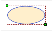
Draw an ellipse | Click the Ellipse button, and the ellipse cursor appears; move the cursor to the position where the ellipse is created, and click the left mouse button to determine the position of the ellipse. Move the mouse, and you can see that the blue temporary ellipse changes in size with Move Stop by Mouse. Click the left mouse button again to complete the drawing of the ellipse at the place where the ellipse arc is determined. | ||
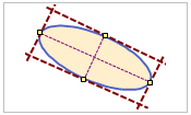
Draw a slanted ellipse | Click the "Ellipse" button, select "Oblique Ellipse" in the pop-up drop-down menu, and the oblique ellipse cursor will appear; move the cursor to the position where the oblique ellipse is created, and click the left mouse button to determine one endpoint of the long/short axis of the oblique ellipse. Move the cursor to the other endpoint of the long/short axis of the oblique ellipse, and click the left mouse button again to determine its long/short axis. Move the cursor to see the shape of a temporary slanted ellipse change with Move Stop by Mouse. Click the left mouse button again at the position where the length of the other axis of the oblique ellipse can be determined to complete the operation of drawing the oblique ellipse. | ||
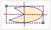
Draw Sector | Click the Fan button. The fan cursor appears. ; Move the cursor to the position where the sector is created (i.e. a diagonal position of the sector Bounds), and click the left mouse button to determine the position of the sector; Move the mouse, and you can see that the size of the blue temporary ellipse changes with Move Stop by Mouse. Click the left mouse button to determine the size of the ellipse; Move the mouse to see a small green square moving on the temporary ellipse with Move Stop by Mouse. Click the left mouse button at the starting position of the sector to determine the starting point of the sector; move the mouse to click the left mouse button again at the ending position of the sector to determine the shape and size of the sector. |
Remarks
End face Object Drawing has the following two methods:
- Right-click an area in Layout where any non-face object is located.
- Click again the button corresponding to the face Object Drawing in the Object Drawing group on the Object Operation tab.
Text
The Text button on the Object Operation tab to draw Text in Layout.
Text Object Drawing | |||
Button |
Explain |
Function and operation method |
Schematic diagram |
Text | Click the "Text" button to display the normal text cursor ; click the left mouse button at the position where the text needs to be added in Layout to display the flashing cursor; enter the text. When you enter text, the text is displayed at the blinking cursor; click the Enter key to start a new line. | ||
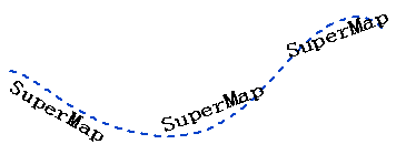
Label Alongline | Creates text along a curve. Click the Drop-down Button of the Text button, select Label Alongline "in the pop-up drop-down menu, and the Alongline Text cursor appears; Create the location of Alongline Text in Layout, click the left mouse button to determine the starting point of Alongline Text, and then draw the path along the line of the text according to the way of drawing a curve; after drawing the path along the line, click the right mouse button to pop up the Alongline Text "dialog box; Enter Alongline Text in the edit box. Click OK to finish drawing Alongline Text. |
Remarks
There are two ways to end text drawing:
- Right-click any area in Layout that is not a text box.
- Click the button for the text Object Drawing in the Text group of the Object Operation tab again.