


Draw Sector
Function Description
- The Sector command is used to draw a sector object. The application provides two ways to draw a sector: one is to draw a circular sector by drawing a circle, and the other is to draw an elliptical sector by drawing an ellipse.
- The drawn sector object is a part of a (ellipse) circle object, so you need to draw a (ellipse) circle object first before drawing a sector object.
Function Entry
- Edit Data tab -> Object Drawing group -> Polygon drop-down list -> Sector.
Operation Instructions
Circular Sector
 |
 |
 |
 |
- In the Edit Data tab, click the Polygon drop-down button in the Object Drawing group, select the Circular Sector command, and the circular sector cursor appears.
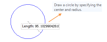
- Move the mouse onto the map, enter the coordinates of the circle center in the parameter input box that appears afterward (you can switch between the two parameter input boxes by pressing the Tab key), then press the Enter key to confirm the center position.
- Move the mouse again and enter the radius (length) in the parameter input box, then press the Enter key to complete drawing the circle.
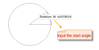
- Continue moving the mouse, enter the start angle of the sector in the parameter input box, and press the Enter key to confirm.
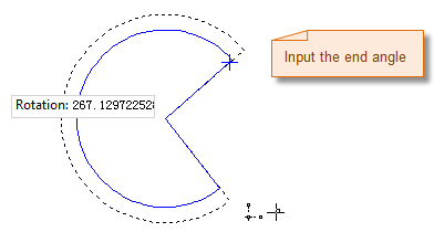
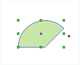
- Move the mouse, enter the sweep angle of the sector in the parameter input box, and press the Enter key to complete drawing the circular sector.
- Right-click to cancel the current drawing operation.
Elliptical Sector
- In the Edit Data tab, click the Sector drop-down button in the Object Drawing group, select the Elliptical Sector command, and the sector cursor appears.
- Move the mouse onto the map. As the mouse moves, the parameter input box will display the current mouse position coordinates in real time. Enter the starting point coordinates of the ellipse in the parameter input box (you can switch between the two parameter input boxes by pressing the Tab key), then press the Enter key to confirm the starting position of the ellipse.
- Move the mouse; the map will display in real time the length of the line connecting the mouse position to the starting point of the semi-axis and the angle between it and the positive direction of the X-axis (you can switch between the two parameter input boxes by pressing the Tab key). Enter the length and angle values in the parameter input box, press the Enter key to execute the input, and complete drawing one semi-axis of the oblique ellipse.
- Continue moving the mouse, enter the length of the other semi-axis of the ellipse in the parameter input box, and press the Enter key to complete drawing the oblique ellipse.
- Continue moving the mouse, enter the start angle of the sector in the parameter input box, and press the Enter key to confirm.
- Move the mouse, enter the sweep angle of the sector in the parameter input box, and press the Enter key to complete drawing the elliptical sector.
- Right-click to cancel the current drawing operation.
 Notes:
Sectors drawn in a line dataset are ordinary line objects, which only record the coordinates of each node on the line. However, sector objects drawn in a CAD dataset are parametric objects, which record corresponding parameters such as center, major semi-axis, minor semi-axis, start angle, and scan angle.