


Draw Polyline
Function Description
The Polyline command is used to create multi-polylines. In practical applications, line objects are mainly used to describe polylines, such as rivers, railways, roads, and power lines. The application also provides multiple ways to draw polylines to meet drawing requirements in different application scenarios.
Function Entry
- Edit Data tab ->Object Drawing group ->Line drop-down menu ->Polyline.
Operation Instructions
Draw a polyline by entering coordinate values
- In the Edit Data tab, in the Object Drawing group, click the Line drop-down button and select Polyline.
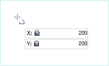
- Move the mouse to the map. As the mouse moves, the coordinate values of the current point are displayed in real-time in the parameter input box. Enter the coordinate value of a polyline node in this box (you can switch between the two input boxes by pressing the Tab key) and press Enter to set the starting point of the polyline.
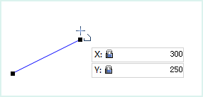
- Move the mouse and enter the coordinate value of the next node in the subsequent parameter box. Press Enter to complete the drawing of the first segment of the polyline.
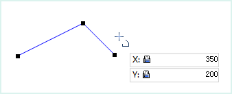
- Continue moving the cursor to a suitable position, enter the X and Y coordinate values, and press Enter to draw the next segment of the polyline.
 Notice:
When the user edits the value in the parameter input box, the input box will be locked, meaning the value in the parameter input box will not change with the mouse movement and only displays the user-entered value. Press the Tab key to switch focus between the X and Y coordinate input boxes (i.e., editing state). Press the Esc key to cancel the locked state of the current parameter input box.
Enter coordinates of the first point Enter coordinates of the second point Enter coordinates of the third point - Repeat the previous step to complete drawing the other segments of the polyline.
- Right-click to end the current drawing operation.
Draw a polyline by entering length and angle
- In the Edit Data tab, in the Object Drawing group, click the Line drop-down button and select the Polyline (Length,Angle) command. The polyline cursor appears.
- Move the mouse to the map. As the mouse moves, the coordinate values of the current mouse position are displayed in real-time in the parameter input box. Enter the coordinate value of a polyline node in this text box (you can switch between the two parameter input boxes by pressing the Tab key) and press Enter to set the starting point of the polyline.
- Move the mouse. As the mouse moves, the map displays in real time the length of the line connecting the mouse position to the previous node (the polyline start point) and the angle between this line and the positive X-axis. Enter the length and angle values in the parameter input boxes (you can switch between the two parameter input boxes by pressing the Tab key) and press Enter to execute the input, completing the drawing of the first segment of the polyline.
- Using the same method, enter the distance between the next node and its previous node, and the angle between the connecting line and the positive X-axis. Press Enter to draw the next segment of the polyline.
- Use the same method to draw other segments of the polyline.
- Right-click to end the polyline drawing operation.