


Function Description
The Polygon command is used to create a polygon. Here, polygon includes arbitrary polygon, regular polygon, orthogonal polygon, etc. Polygon is one of the most commonly used area objects. It is often used to represent closed area features, such as administrative regions, soil, vegetation, lakes, etc. It can also represent some special geographical area feature types, such as islands, rings, enclaves, etc.
Function Entry
- Edit Data tab ->Object Drawing group ->Polygon drop-down list ->Polygon.
Operation Instructions
Draw Polygon by Entering Coordinate Values
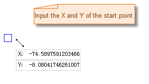
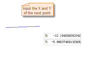
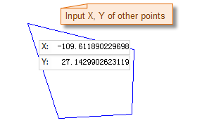
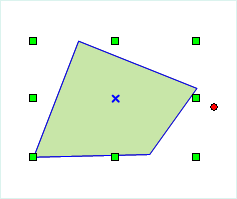
The process of drawing a polygon is shown in the figure below:
 |
 |
 |
 |
The process of drawing a polygon by holding the Q key is shown in the figure below:
Draw Polygon by Length and Angle
- In the Edit Data tab, in the Object Drawing group, click the Polygon drop-down button and select Polygon(Length, Angle).
- Move the mouse to the map. As the mouse moves, the coordinates of the current point are displayed in real time in the parameter input box. Enter the coordinate values of the first node of the polygon in the box (you can switch between the two parameter input boxes by pressing the Tab key) and press the Enter key to confirm the starting position of the polygon.
- Move the mouse. As the mouse moves, the length of the line between the current mouse position and the previous control point and its angle relative to the positive X-axis are displayed in real time on the map. Type the length value and angle value in the parameter input boxes (you can switch between the two parameter input boxes by pressing the Tab key), and press the Enter key to execute the input and confirm the drawing of the first segment of the polygon.
- Enter the distance (length) between the next node and the previous node and the angle between the connecting line and the positive X-axis (you can switch between the two parameter input boxes by pressing the Tab key), and press the Enter key to draw the next segment of the polygon.
- Repeat the above steps to continue drawing other segments of the polygon.
- Right-click to end the current drawing operation.
Draw a Regular Polygon
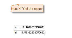
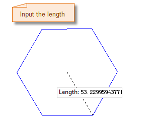
The process of drawing a regular polygon is shown in the figure below:
 |
 |
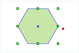 |
| Specify the center point of the regular polygon | Specify the length and angle of the regular polygon | Result of regular polygon |
- In the Edit Data tab, in the Object Drawing group, click the Polygon drop-down button and select Regular Polygon.
- A Parameters dialog box appears. Enter the number of sides of the regular polygon to be drawn. The number of sides must be greater than 3. The default number of sides is 5.
- Move the mouse to the map. As the mouse moves, the coordinates of the mouse position are displayed in real time in the parameter input box. Enter the coordinate values of the center point of the regular polygon in the box (you can switch between the two parameter input boxes by pressing the Tab key) and press the Enter key to confirm.
- Move the mouse again, then enter the radius (length) of the circumscribed circle of the regular polygon and the angle between the circumscribed circle radius and the horizontal axis in the parameter input boxes. Press the Enter key to complete the drawing of the regular polygon.
Auto-Face (Draw by Area Intersection)
The process of auto-face (draw by area intersection) is shown in the figure below:
- In the Edit Data tab, in the Object Drawing group, click the Polygon drop-down button and select Auto-Face (Draw by Area Intersection).
- Draw an area that intersects existing area objects. The closed region formed by the drawn area and the common boundary becomes the new area object.
Auto-Face (Draw by Line Intersection)
The process of auto-face (draw by line intersection) is shown in the figure below:
- In the Edit Data tab, in the Object Drawing group, click the Polygon drop-down button and select Auto-Face (Draw by Line Intersection).
- The drawn line intersects an existing region object, and the enclosed area formed by the line and the common side is the new region object. If the closed region formed by the drawn line and the existing region object lies entirely inside the original region, the drawing will not succeed.