


Feature Description
Creating models involves intelligently connecting multiple professional geographic data processing tools according to preset business logic to form an automated spatial analysis workflow. By programming and pipelining complex geographic data processing procedures, it effectively avoids manual step-by-step operations, significantly improving work efficiency. It is suitable for batch data processing (such as multi-region analysis, periodic data updates, etc.), substantially enhancing productivity.
Operation Instructions
- Open Model Builder: In the Ribbon-style interface, the Model Builder is hidden. You can open it through any of the following entries:
- Workspace Manager->GPA node context menu->Create GPA Model.
- Start tab->Browse group->GPA dropdown menu->New Model.
- Set Data Source: Provides two methods to set the data source for storing intermediate and result data during execution of the GPA model.
- Set the data source in Workspace Manager. For details, refer to Open or New data source.
- Use the Data Source Management tool: Drag the Open Datasource tool to the canvas to pass data as source data.
- Add Tools: Select tools from the toolbox and drag them directly to the canvas.
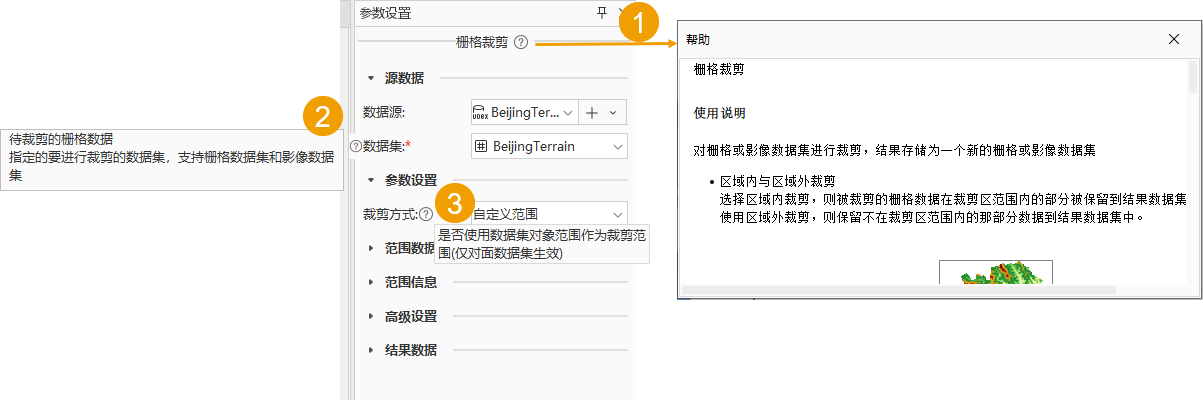
- Parameters: Double-click a tool or variable node to set related parameters in the pop-up parameter panel. Mandatory parameters cannot be empty. View parameter help through any of the following three entries or open the corresponding help:
① Click the help button here to open the tool's help dialog, where you can view the tool's instructions for use and detailed descriptions of all parameters.
② Hover the mouse over a parameter; a help button will appear to its left. Hover over the help button to view instructions for that parameter.
③ If there is a help button to the right of a parameter, hover over it to quickly view instructions for that parameter.
- Connect Tools: Hover the mouse over the data output port of the previous tool node until the cursor changes to a "crosshair." Then, hold the left mouse button and move to the input port of the next tool node. Release the mouse and select the input data type.

New canvas style Traditional canvas style - Remove Tools: During model adjustment, select a tool or variable node and press the Delete key to remove it.
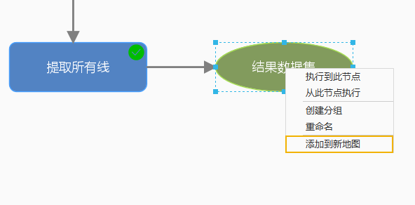
- Set Data Preview: Select the node you want to view data for and click the preview button in the toolbar above. After the model runs, you can view the processed result data in real-time using the preview button on the tool's output port. For traditional canvas style, after running the model, you can open and browse data via the "Add to New Map" option in the variable node's context menu.
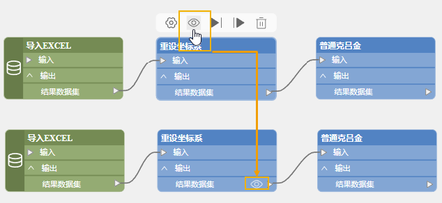
New canvas style Traditional canvas style - Run Model: After completing model construction, click the Run button in the GPA group under the GPA tab to run the entire GPA model. After running, the Task Manager window will automatically open to display the model's execution status.
Related Topics