


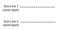
When creating line symbols in the linear symbol editor, line symbols are composed of several sublines. By using different forms and styles of sublines, the required line symbols can be constructed. Therefore, the basic element of a line symbol is the subline. For example, the following figure shows the basic way sublines constitute a line symbol.
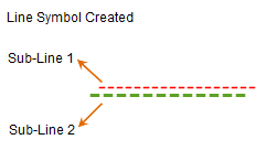
As shown in the figure below, to create a specific line symbol, it consists of two sublines: subline 1 and subline 2. Both sublines are of the short horizontal line type. According to the requirements of the line symbol being created, apply appropriate horizontal offset and vertical offset to the sublines, and set their color style and line width to complete the line symbol. The linear symbol editor provides various types of sublines, allowing users to build the desired line symbols by modifying the style and appearance of these sublines.
 |
Composition method: Apply a horizontal offset of 2 mm and a vertical offset of 2 mm to subline 1, fix the color of subline 1 as: red RGB(255, 0, 0); fix the color of subline 2 as: green RGB(0, 255, 0), and set the line width to 1 mm. |
 |
Subline Types
In the linear symbol editor, creating line symbols is based on sublines. The editor provides multiple subline types. After adding a subline in the linear symbol editor, you can select its type from a dropdown list, which includes the basic subline types available.
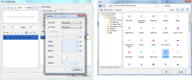
Additionally, sublines can be composed of specific symbols. As shown in the figure below, the subline type is a symbol subline, meaning it consists of symbols. The virtual-real mode of the subline (for details on virtual-real mode, refer to the section below on virtual-real mode) can adjust how symbols are distributed in the subline, such as the spacing between symbols. To set the subline type as a symbol subline, select the Custom Symbols type from the subline type list.
When the subline type is set to symbol subline, you can further specify the symbols that constitute the subline and adjust its virtual-real mode.
Subline Virtual-Real Mode
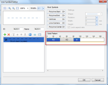
The virtual-real mode of a subline determines which segments of the subline are drawn (solid) and which are not drawn (dashed), creating sublines similar to the short horizontal line type. You can directly set the lengths of the solid and dashed parts by entering numerical values. The values follow a "solid dashed" cycle in millimeters, with precision to one decimal place. Enter them as numbers separated by spaces, e.g., "4 2" means a solid part length of 4 mm and a dashed part length of 2 mm. If all values are deleted or only one value is entered, the subline becomes a solid line.
For the short horizontal line shown below, its virtual-real mode is set as indicated by the circled content, where 4 represents a solid part length of 4 mm, and 2 represents a dashed part length of 2 mm.
How does virtual-real mode affect the drawing effect of sublines? The following sections explain in detail. Since sublines have different types, the same virtual-real mode may be interpreted differently for some subline types. The main interpretation methods for how virtual-real mode affects sublines are as follows.
Short Horizontal Line Type:
After adding a subline, if you set the subline type to short horizontal line (system line type), it will have a default virtual-real mode. Deleting the virtual-real mode makes the subline solid, meaning the solid line is the base subline for short horizontal lines. Applying virtual-real mode achieves the short horizontal line type. Therefore, the effect of virtual-real mode is explained based on the solid line.
As shown in the figure below, if the subline is a solid line and virtual-real mode is set to solid part value 20 and dashed part value 40, the subline will be drawn as follows:
- Starting from the drawing start point of the subline, draw a solid segment of length 20, which is the set solid part 20;
- Next, do not draw any content for a distance of 40, which is the blank dashed part 40;
- Then repeat the above two drawing operations.
In summary, for such sublines, virtual-real mode means: for the solid part of the subline, draw content for the solid part length, and for the dashed part, do not draw anything for the dashed part length. The unit for length values is 0.1 mm.
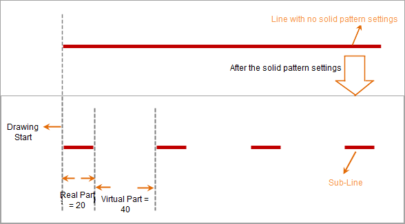 |
| Diagram of Subline Virtual-Real Mode for Short Horizontal Lines |
In the linear symbol editor, subline types with virtual-real mode drawing as described above include: parallel double lines (center aligned), parallel double lines (top aligned), and parallel double lines (bottom aligned).
Short Vertical Line Type:
Subline types similar to " " are called short vertical line sublines. As shown in the figure below, if virtual-real mode is set to solid part value 20 and dashed part value 40, the short vertical line subline will be drawn as follows:
- Starting from the drawing start point of the subline, at a distance of 20 (solid part=20), draw a short vertical line;
- Next, starting from the previously drawn short vertical line, at a distance of 40 (dashed part=40), draw another short vertical line;
- Then, starting from the previously drawn short vertical line, at a distance of 20 (solid part=20), draw another short vertical line, and so on, completing the virtual-real mode drawing for the short vertical line subline.
 |
| Diagram of Subline Virtual-Real Mode for Short Vertical Lines |
In the linear symbol editor, subline types with virtual-real mode drawing as described above include: staggered up and down, short vertical line (center aligned), short vertical line (top aligned), and parallel double lines (bottom aligned).
Long-Short Alternating Type:
Subline types similar to " " are called long-short alternating sublines, composed of alternating long and short vertical line elements. As shown in the figure below, if virtual-real mode is set to solid part value 20 and dashed part value 40, the long-short alternating subline will be drawn as follows:
- Starting from the drawing start point of the subline, at a distance of 20 (solid part=20), draw a long vertical line;
- Next, starting from the previously drawn vertical line, at a distance of 40 (dashed part=40), draw a short vertical line;
- Then, starting from the previously drawn vertical line, at a distance of 20 (solid part=20), draw another long vertical line, and so on, repeating steps 2 and 3 to complete the virtual-real mode drawing.
 |
| Diagram of Subline Virtual-Real Mode for Long-Short Alternating Type |
In the linear symbol editor, subline types with virtual-real mode drawing as described above include: long-short alternating (upward), long-short alternating (downward), long-short alternating (long up short down), and long-short alternating (short up long down).
Diagonal Line Type:
Subline types similar to " " are called diagonal line sublines, composed of diagonal lines at a certain inclination angle. As shown in the figure below, if virtual-real mode is set to solid part value 40 and dashed part value 80, the diagonal line subline will be drawn as follows:
- Starting from the drawing start point of the subline, draw a diagonal line with its start point at the drawing start and end point at a distance of 40 (solid part=40);
- Next, starting from the end point of the previous diagonal line, do not draw any content for a distance of 80 (dashed part=80), which is the blank dashed part;
- Then, draw the next diagonal line with its start point at the end of the previous diagonal line and end point at a distance of 40 (solid part=40) from that start point, and so on, repeating steps 2 and 3 to complete the virtual-real mode drawing.
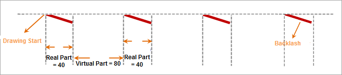 |
| Diagram of Subline Virtual-Real Mode for Diagonal Line Type |
In the linear symbol editor, subline types with virtual-real mode drawing as described above include: diagonal line (/), and diagonal line (\).
Diagonal Line (Staggered Up and Down) Type:
Subline types similar to " " are called diagonal line (staggered up and down) sublines, composed of diagonal lines with different inclination directions. As shown in the figure below, if virtual-real mode is set to solid part value 40 and dashed part value 80, the diagonal line (staggered up and down) subline will be drawn as follows:
- Starting from the drawing start point of the subline, draw a diagonal line with its start point at the drawing start and end point at a distance of 40 (solid part=40);
- Next, draw the next diagonal line with its start point at the end of the previous diagonal line and end point at a distance of 80 (dashed part=80) from that start point;
- Then, draw the next diagonal line with its start point at the end of the previous diagonal line and end point at a distance of 40 (solid part=40) from that start point, and so on, repeating steps 2 and 3 to complete the virtual-real mode drawing.
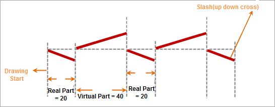 |
| Diagram of Subline Virtual-Real Mode for Diagonal Line (Staggered Up and Down) Type |
In the linear symbol editor, the subline type with virtual-real mode drawing as described above is: diagonal line (staggered up and down).
Symbol Type:
Subline types similar to " " or "
 " are called symbol type sublines, composed of specific symbol elements. As shown in the figure below, if virtual-real mode is set to solid part value 20 and dashed part value 40, the symbol type subline will be drawn as follows:
- Starting from the drawing start point of the subline, at a distance of 20 (solid part=20), draw a symbol element;
- Next, starting from the previously drawn symbol element, do not draw any content for a distance of 40 (dashed part=40), which is the blank dashed part;
- Then, at a distance of 20 (solid part=20) from the end point of the previous element, draw another symbol element, and so on, repeating steps 2 and 3 to complete the virtual-real mode drawing.
 |
| Diagram of Subline Virtual-Real Mode for Symbol Type |
In the linear symbol editor, subline types with virtual-real mode drawing as described above include: cross symbol (×), cross symbol (upward), cross symbol (downward), custom symbols (relative angle), and custom symbols (fixed angle).
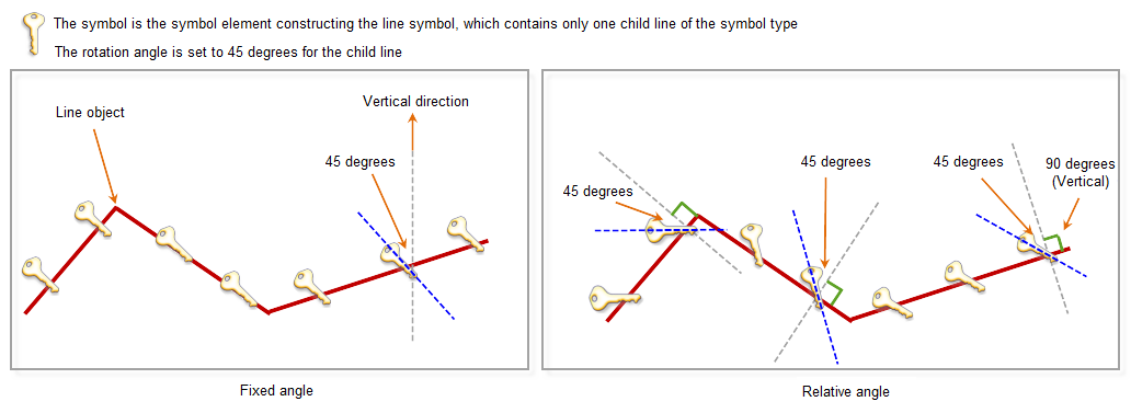
The figure below illustrates the difference between the two subline types: custom symbols (relative angle) and custom symbols (fixed angle). Both are symbol type sublines, but they differ as follows:
- Custom symbols (fixed angle): If the rotation angle is set for the symbols constituting the subline, all symbols in the subline maintain a consistent rotation angle. The 0-degree reference point is the vertical upward direction, with counterclockwise as the increasing angle direction. When symbolizing a line object, whether straight or polyline, the symbols in this subline always maintain the same direction.
- Custom symbols (relative angle): If the rotation angle is set for the symbols, it may not be uniform. For example, when symbolizing a polyline object, the 0-degree reference point changes with the direction of each segment, where the perpendicular to the segment's forward direction is 0 degrees, and counterclockwise is the increasing direction. For a curve object, the 0-degree reference point is perpendicular to the tangent direction, with counterclockwise as the increasing direction.
In the figure below, the red polyline is the line object to be symbolized. To show the difference between custom symbols (relative angle) and custom symbols (fixed angle), the symbolized line object is retained after applying the line symbol.
 |
Subline Offset
In the online symbol editor, a newly added subline has a default offset of horizontal offset=0 and vertical offset=0, with units in millimeters. You can control the relative positions between sublines by setting their offsets.
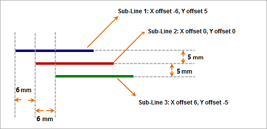 |
| Diagram of Subline Offset |
Subline End Symbol
Adding an end symbol to a subline allows you to place specified symbols at special positions on the subline. These positions include: head of the subline, tail of the subline, middle point of the subline, segment center of the subline, and polyline center of the subline. The effects of adding end symbols are further explained through diagrams below.
- Adding End Symbol at Polyline Head
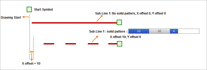
As shown in the figure below, this demonstrates the effect of adding an end symbol at the head of the subline, i.e., placing a specified symbol at the drawing start point. The figure shows two sublines with different types, virtual-real modes, and styles, illustrating the result after adding the head end symbol.

Adding End Symbol at Polyline Head - Adding End Symbol at Polyline Tail
As shown in the figure below, this demonstrates the effect of adding an end symbol at the tail of the subline, i.e., placing a specified symbol at the end point. The figure shows two sublines with different types, virtual-real modes, and styles, illustrating the result after adding the tail end symbol.
Adding End Symbol at Polyline Tail - Adding End Symbol at Middle Point
Adding an end symbol at the middle point of the subline is more noticeable when symbolizing line objects. If a subline in a line symbol has an end symbol added at the middle point, when using this line symbol to symbolize a line object, the specified end symbol will be placed at all nodes of the object (excluding the two endpoints). As shown below, the effect of setting the subline to add an end symbol at the middle point can only be previewed in the linear symbol editor using the "polyline" preview. The effect after symbolizing a polyline object is shown in the figure.
Adding End Symbol at Middle Point - Adding End Symbol at Segment Center
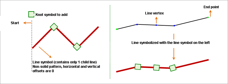
Adding an end symbol at the segment center of the subline is more noticeable during line object symbolization. If a subline is set to add an end symbol at the segment center, when symbolizing a line object, the specified end symbol will be placed at the midpoint of each segment between adjacent nodes. As shown below, the effect after setting the subline to add an end symbol at the segment center and symbolizing a polyline object is illustrated.

Adding End Symbol at Segment Center - Adding End Symbol at Polyline Center
Adding an end symbol at the polyline center of the subline is more noticeable during line object symbolization. If a subline is set to add an end symbol at the polyline center, when symbolizing a line object, the midpoint of the object is calculated, and the specified end symbol is placed at that position. As shown below, the effect after setting the subline to add an end symbol at the polyline center and symbolizing a polyline object is illustrated.
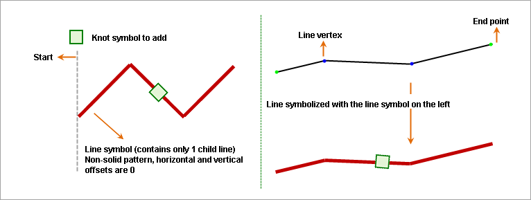
Adding End Symbol at Polyline Center
Related Topics
Line Symbol Subline Management
Setting Subline Virtual-Real Mode