


Feature Description
In surveying and mapping, commonly used standard directions include the true meridian direction, magnetic meridian direction, and coordinate vertical axis direction, abbreviated as true north direction, magnetic north direction, and grid north direction, collectively known as the three north directions, as shown in Figure 1. For medium and small-scale topographic maps, drawing the three north directions is typically required.
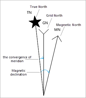 |
| Figure: Schematic of a Three-North Arrow |
Grid North Direction
Grid north direction, also known as map north or grid north, refers to the "up" direction indicated by the vertical grid lines on a map. In the Gauss-Krüger planar rectangular coordinate system, the direction pointed by the vertical coordinate axis or parallel to it is the grid north direction.
True North Direction
The direction pointing to the North Pole from any point on the ground is called true north. For a map, the north direction of the center meridian of the map sheet is generally used as the true north direction.
In Gauss-Krüger projection, except for the center meridian which projects as a straight line, all other meridians project as arcs converging toward the pole. Therefore, for all meridians except the center meridian, there is an angle between their projection and the vertical coordinate line, known as the meridian convergence angle.
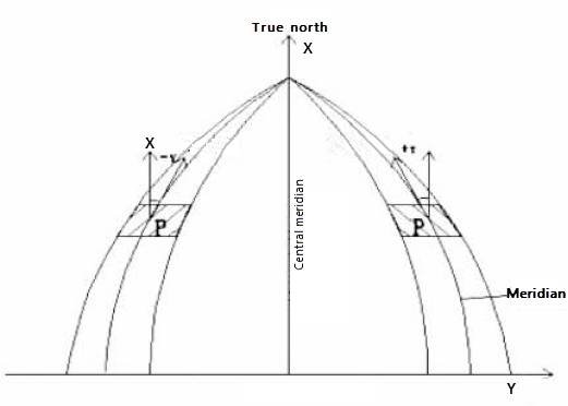 |
| Figure: True North Direction and Meridian Convergence Angle |
The meridian convergence angle is the angle between the true meridian of a point on the Earth's ellipsoid surface and the prime meridian of the projection zone where the point is located, that is, the angle between the coordinate north direction of the Gauss planar rectangular coordinate system and the true north direction. Relative to the true north direction, when the north end of the vertical coordinate axis is located east, it is called east deviation with a positive angle value; when located west, it is called west deviation with a negative angle value.
Currently, the meridian convergence angle can be calculated using formula methods or lookup tables. In the application, the meridian convergence angle is automatically calculated using the map center point coordinates based on the following formula.
Formula Method
Calculate the meridian convergence angle using known GCS (B, L). According to the approximate formula for meridian convergence angle in "Principles and Methods of Digital Mapping" published by China University of Mining and Technology Press:
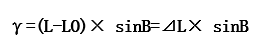
L: GCS longitude; LO: prime meridian longitude; △L: longitude difference, i.e., the longitude difference between a point and the prime meridian; B: GCS latitude.
For example: The GCS of map center point P in the layout is: B=18°18′32.82820″, L=109°18′36.94903″. Calculate the meridian convergence angle for point P in the 6-degree zone 19. LO=6°×19-3°=111°γ=(109°18′-111°)×sin18°18′32.82820″=-0°31′50.59″
Magnetic North Direction
Magnetic north direction refers to the north indicated by a compass, primarily because the Earth's magnetic poles do not coincide with the geographic North and South Poles. Therefore, the compass indicates magnetic north rather than true north, and the specific location of magnetic north changes over time. The geomagnetic poles are near the Antarctic and Arctic but do not coincide with them; one is approximately at 72°N, 96°W, and the other at 70°S, 150°E.
The geomagnetic North Pole is the point on the Earth's surface where the Earth's magnetic field direction is vertically downward. It differs from the geographic North Pole and is constantly moving at a speed of 20.5 meters per day. The magnetic North Pole is approximately 1500 km from the geographic North Pole. Its position also fluctuates daily, tracing an elliptical path, with an average northward movement of 40 meters per day. To draw the magnetic north direction in daily mapping, the magnetic declination can be determined to calibrate the magnetic north direction.
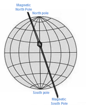 |
| Figure: Magnetic North Direction Illustration |
Magnetic declination is the angle between magnetic north and true north, that is, the angle between the magnetic meridian and the prime meridian. Relative to the magnetic north direction, deviation eastward toward true north is called east declination with a positive angle, while deviation westward is called west declination with a negative angle.
Magnetic declination is measured using a magnetic declination meter. Currently, magnetic declination measurement mainly adopts two methods: continuous long-term tracking observation at fixed geomagnetic observatories, and irregular measurements at mobile field points. Since the site selection and construction standards for fixed geomagnetic observatories are very high, it is not feasible to build too many. Therefore, a combination of a few geomagnetic observatories and numerous field measurement points is the optimal mode for geomagnetic field measurement.
Generally, during mapping, the actual measured value of magnetic declination is marked on the map. Thus, when labeling the magnetic north direction, users can input the magnetic declination obtained during mapping to accurately mark the magnetic north direction.
You can also use data provided by the World Magnetic Model (WMM) by entering the time and specific latitude and longitude to obtain a magnetic declination value based on model monitoring stations. The WMM is jointly developed by the National Geophysical Data Center (NGDC, Boulder CO, USA) (now the National Centers for Environmental Information, NCEI) and the British Geological Survey (BGS, Edinburgh, Scotland). The model is updated every five years, and the current model expires on December 31, 2019. For details, refer to World Magnetic Model.
Operation Steps
- Select a map in the layout where you need to draw a north arrow.
- Click the Features tab -> Objects group -> North Arrow -> Three North Arrow.
- Click and drag the mouse at the desired position in the current layout to draw the three north arrow. The application will automatically calculate the meridian convergence angle based on the map center point coordinates and label the true north direction accordingly. The magnetic north direction requires the user to specify the magnetic declination to take effect; otherwise, it will coincide with the true north direction.
Note: Planar coordinate systems do not support drawing a three-north arrow. When the map coordinate is a planar coordinate system, the Three North Arrow button is unavailable.
- Double-click the three north arrow; or select the north arrow, right-click, and choose "Properties" from the context menu to open the "North Arrow Property" window. The property window displays parameters such as magnetic declination, rotation angle, width, height, etc.
- Meridian Convergence Angle: This angle is automatically calculated by the application based on the map coordinate system using the map center point coordinates and is not editable. When the meridian convergence angle is 0, it indicates that the current map coordinate system has no center meridian, so the true north direction coincides with the grid north direction.
- Magnetic Declination: The default value is 0, in degrees. Users must manually input the magnetic declination for the current map. The application rotates based on the true north direction using the input magnetic declination angle to represent the magnetic north direction. Deviation eastward from true north is positive, and deviation westward is negative.
- Users can adjust the size of the three north arrow by setting the rotation angle, height, and width. For parameter descriptions, refer to "Drawing a North Arrow".
Related Topics