


Drawing Settings
Feature Description
Drawing settings is used to configure auxiliary behaviors during object creation and editing, helping users control automatic processing, node display, editing refresh, and auxiliary line styles when drawing, selecting, and editing objects.
Function Entry
- Edit Data tab > Edit the settings group > Drawing Settings drop-down menu.
Operation Instructions
Set Drawing and Editing Options
- In the Edit Data tab, click the Drawing Settings drop-down button.
- Select the settings item to enable or configure from the drop-down menu.
- Adjust the following settings items according to the drawing and editing task.
- Auto-connect Lines: When enabled, line objects that snap to the start or end point of another line object will be auto-connected into one line object in drawing order.
- Auto-close Lines: When drawing a polyline, curve, polyline, or free curve, the current line object will be automatically closed.
- Auto-split Lines: When drawing a line feature, the original object and the newly drawn line feature will be automatically split at intersections, generating multiple line objects.
- Auto-cut Polygons: When drawing a polygon feature, the intersecting part between the currently drawn polygon feature and other polygon objects will be automatically cut to obtain a new object.
- Parametric Drawing: Input parameters such as coordinates, length, and angle when drawing objects to complete the objects with specified parameters.
- Draw Polyline: Draw a continuous line object composed of multiple types of line segments.
- Real-time Refresh: When enabled, the map will be refreshed in real-time after feature editing is completed to avoid retaining editing traces; when disabled, the map will not be refreshed immediately after feature editing is completed.
- Show Feature Vertices: When enabled, the nodes of drawn objects will be displayed during the drawing process.
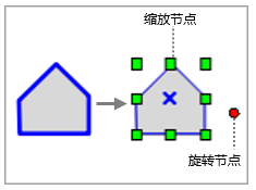
- Show Editing Assistance Points: Controls whether Zoom nodes and Rotate nodes are displayed when selecting objects in editing mode. When selected, nodes are displayed; when selection is canceled, selected objects do not display nodes by default.
- Sticky Move Tolerance: Set the tolerance value for moving objects. When moving an object with the mouse, if the movement distance is less than the tolerance value, the move will not be executed. When the tolerance value is 0, this function is disabled.
- Maximum Visible Nodes Number: Set the maximum number of nodes that can be displayed on the map. If the number of object nodes exceeds this value, the system will not display the object nodes.
- Maximum Editable Records: Set the maximum number of objects that can be edited at one time. If the number of selected objects exceeds this value, the system will only apply to feature editing within the limit range.
- Batch Editing Maximum Record Count: Set the number of records for automatic submission in batch editing. When this record count is reached, the system will automatically submit the current editing records.
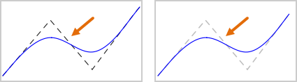
- Auxiliary Line Style: Set the display style of auxiliary lines when drawing objects such as B-spline curves, three-point arcs, Bezier curves, and straight lines.
 Notes:
- When moving objects, the snapping function affects the move result. If the sticky move tolerance is 0 and the snapping function is enabled, moving an object may snap to object nodes, potentially preventing the object from moving as expected. It is recommended to disable the snapping function when moving small distances.
- Using keyboard arrow keys to move objects is not affected by the sticky move tolerance.
- Setting the maximum visible nodes number, maximum editable records, or batch editing maximum record count too large may affect map display and editing response efficiency.