


Display Control
The Display Control group organizes common parameters for layer properties. For details, please refer to Setting Common Layer Properties.
No Value
- No Value: Refers to pixel values with no practical meaning in image data. Users can directly input a pixel value (or click the pick button to select from the image layer) to designate it as no value.
- For single-band image layers: Input pixel value directly.
- For multi-band image layers: Input RGB color values.
- No Value Transparent: Controls display color for no-value areas. When checked, no-value areas will be displayed as transparent.
- No Value Color: Available when "No Value Transparent" is unchecked. Select a color from the dropdown button to display no-value areas.
 Note:
Note:No values on image dataset attribute panels are represented as RGB decimal integers. The no values on image dataset layer properties panel correspond to color modes. For example, when color mode is RGB and no value is 96555, it displays as (1,21,43) on layer properties panel.
Background Value
Designates specified pixel values as background values to change display colors in corresponding areas.
- Background Value: Directly input a value or use pick button to select from map.
- For single-band image layers: Input pixel value directly.
- For multi-band image layers: Input RGB color values.
- Background Transparent: When checked, background areas become transparent. When unchecked, select a background color from dropdown menu.
Transparent Color
Sets specified pixel value areas as transparent in image layers.
- Transparent Color: Check to enable pixel selection via pick button. Selected pixel areas become transparent.
- Transparent Color Tolerance: Sets tolerance range for transparent colors. Given original color (r, g, b) and tolerance a, transparent range becomes (r-a, g-a, b-a) to (r+a, g+a, b+a). Default 0, valid range [0,255] integers.
Brightness
Adjusts brightness level of image layers.
Input value directly or use spin button for adjustment.
Contrast
Adjusts contrast level of image layers.
Input value directly or use spin button for adjustment.
Interpolation Method
Determines image display quality during scaling operations by mapping original pixels to larger/smaller pixel sets.
- Nearest Neighbor: Simple method with fast processing but lowest display quality.
- Low Quality: Performs pre-filtering for quality downsampling, poor quality when enlarged.
- High Quality: Higher display quality during scaling with longer processing time.
- High Quality Bilinear: Uses high-quality bilinear interpolation for optimal scaling results.
- High Quality Bi-cubic: Uses bi-cubic interpolation for highest output quality with longest processing time.
Display Method
Display settings vary between single-band and multi-band images. Modifying display methods is unavailable for 32-bit and 24-bit depth images.
Single-band Image
- Default Display: No stretching applied. Uses color table if available, otherwise grayscale.
- Stretch Display: Color-based stretching.
- Color: Enable to use specified color. Disabled mode uses color table (or grayscale). Select predefined colors or customize via edit button. Available for 8-bit and 16-bit images.
- Stretch Method: Default Percent Clip. See Image Stretching Methods.
- Color Table Display: Displays image with specified color scheme. Available for 8-bit and 16-bit images.
- Grid Function Display: Displays using raster functions: 3D Hillshade or 3D Orthophoto. See Setting Raster Layer Properties.
Multi-band Image
- Combination Display: Stretches multi-band images via specified color modes.
- Color Mode: Sets image display color mode, default RGB. Modes explained below:
Color Mode Description RGB Combines Red, Green, Blue channels. Primarily used in display systems.
CMYK Available when stretch method isn't Percent Clip. Combines Cyan, Magenta, Yellow, Black for printing systems.
RGBA Available when stretch method isn't Percent Clip. Adds Alpha channel for transparency control in display systems.
CMY Available when stretch method isn't Percent Clip. Cyan, Magenta, Yellow combination for printing systems.
YIQ Available when stretch method isn't Percent Clip. Used in NTSC television systems.
YUV Available when stretch method isn't Percent Clip. Used in PAL television systems.
YCC Available when stretch method isn't Percent Clip. Used in JPEG image format.
- Stretch Method: Default Percent Clip. See Image Stretching Methods.
- Color Mode: Sets image display color mode, default RGB. Modes explained below:
- Single Band Stretch Display: Color-based stretching for specified band.
- Bands: Select display band.
- Color: Enable to select predefined colors or customize. Available for 8-bit and 16-bit images.
- Stretch Method: Default Percent Clip. See reference above.
- Single Band Color Display: Color display for specified band.
- Bands: Select display band.
- Color: Select predefined colors or customize. Available for 8-bit and 16-bit images.
- Single Band Grid Function Display: Displays single-band data using 3D Hillshade or 3D Orthophoto. See Setting Raster Layer Properties.
Gamma
Adjusts nonlinear brightness/contrast to enhance image details. Range: [0,10] with two decimal precision. Unavailable for grid function display methods.
-
Gamma=1: No correction applied.
-
Gamma>1: Enhances dark areas, reduces bright area details.
-
Gamma<1: Enhances bright areas, reduces dark area details.
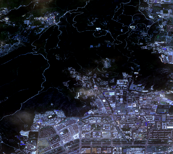 |
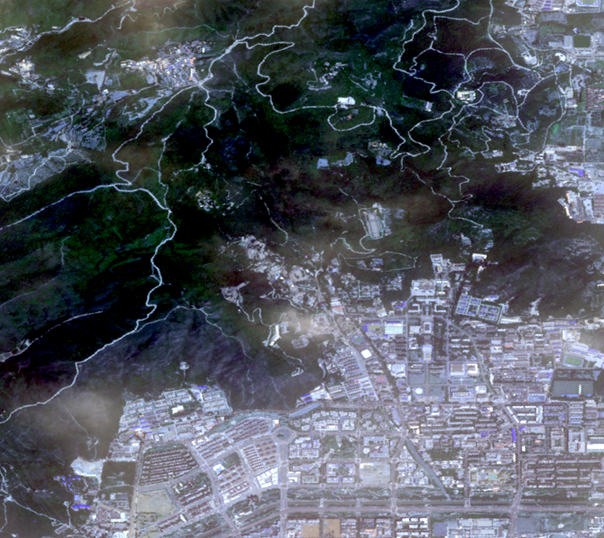 |
| Fig: Gamma=1 | Fig: Gamma=2 |
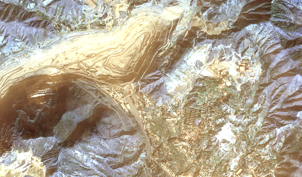 |
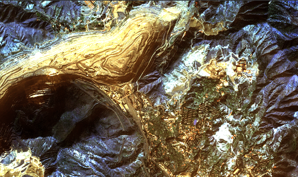 |
| Fig: Gamma=1 | Fig: Gamma=0.4 |
Display Orthorectified Image
Available when dataset contains RPC information. Check to display elevation-corrected image.
When enabled, three elevation setting methods:
- Fixed Value: Default elevation from image files. Editable.
- SRTM V4: Uses elevation data from deployed remote sensing package.
- Custom: Specify DEM data in Tiff/GeoTIFF, Erdas Image, PCIDSK or ArcInfoGrid format. ArcInfoGrid requires Add Folder button.
Related Topics
Setting Common Layer Properties
Setting Vector Layer Properties
Setting Raster Layer Properties