


Example Description
SuperMap supports calculating parameter values for commonly used four-parameter and seven-parameter transformations through operations such as selecting common points, coordinate transformation models, and accuracy evaluation. Users can utilize these parameter values to convert the coordinate system of data results.
Example Description
A user has vector data of a certain area in the Xi'an 1980 coordinate system and wishes to convert it to the 2000 National Geodetic Coordinate System. The user has measured some control points within the survey area, which have coordinates in both the Xi'an 1980 system and the 2000 National Geodetic Coordinate System. The following provides a detailed explanation of the operational steps using this data conversion as an example.
Preparation
Select control points with coordinates in both the Xi'an 1980 coordinate system and the 2000 National Geodetic Coordinate System as the common points file.
Common Points
The selection of common points is crucial for calculating transformation parameters. Users need to select control points that have coordinate results in both coordinate systems as common points.
- Basic Principles for Selecting Common Points: High grade, high accuracy, uniform distribution, coverage of the entire conversion area, and small local deformation.
- Quantity Requirements for Common Points: Generally, for conversion to the 2000 system, the number of common points should be no less than 6, and the number of external check points should also be no less than 6. All points should be uniformly distributed to cover the entire conversion area. Considering possible gross errors, it is advisable to prepare several additional common points as backups. In summary, as many common points as possible should be selected.
Function Entrance
In the Start tab -> Data Processing group -> Project drop-down button -> Calculate Transformation Model Parameters.
Operational Instructions
- Settings Transformation Model: Click the drop-down button on the right of Model Method to select the transformation model method, including Position Vector (7-para) (Position Vector Transformation), Coordinate Frame (7-para) (Coordinate Frame Rotation Transformation), China_3D_7P (7-para) (3D Seven-Parameter Transformation Model), China_2D_7P (7-para) (2D Seven-Parameter Transformation Model), and China_2D_4P (7-para) (2D Four-Parameter Transformation Model).
The selection of the transformation model is influenced by the coordinate system of the control points and the conversion area. The choice of model method depends on the specific situation. The "Technical Specification for Geodetic Control Point Coordinate Transformation" provides the scope of application for transformation models. Users can select the transformation model based on the coordinate system of the source data control points and the applicable area range of the transformation model. For information on transformation models and their scope of application, please refer to Transformation Model.
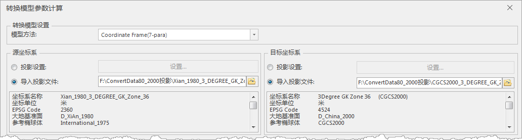
Figure: "Calculate Transformation Model Parameters" Dialog - Set the types of coordinate systems for mutual conversion, i.e., the source coordinate system and the target coordinate system. The program supports geographic coordinate systems, projected coordinate systems, and mutual conversion between the two:
- Source Coordinate System Settings: Set the coordinate system of the source data at the source coordinate system. Coordinate system settings can be done in the following two ways:
- Projection Settings: Select the Projection Settings radio button, click the Settings button, and choose a geographic coordinate system or projected coordinate system provided by the program that matches the source point data, setting it as the current coordinate system. For specific operations on setting projections, please refer to Projection Settings.
- Import Projection File: Select the import projection file radio button, click the Select button, choose the projection information file, and import it.
- Target Coordinate System Settings: Set the coordinate system type for the converted data.
- Source Coordinate System Settings: Set the coordinate system of the source data at the source coordinate system. Coordinate system settings can be done in the following two ways:
- Common Point Settings: Input common points that have coordinates in both the source coordinate system and the target coordinate system. The coordinate format of the common points must be consistent with the source coordinate system and target coordinate system set in the previous step; otherwise, the program will提示 control point coordinate format error.
Common points can be added in three ways: Create a Matching Dot String, Import Common Points File, and Manual Input:
- Create a Matching Dot String: When common points exist in the data source as datasets, you can separately specify the source data and the select fields of common points in the target dataset, establishing a connection between the source data and the target dataset through specified field values. Click the Create a Matching Dot String button in the common point settings toolbar to perform operations in the Create a Matching Dot String dialog.
- Import Common Points: Click the import button in the common point settings toolbar to import a common points file (.txt). The format of the common points file (.txt) is参考 as shown below:
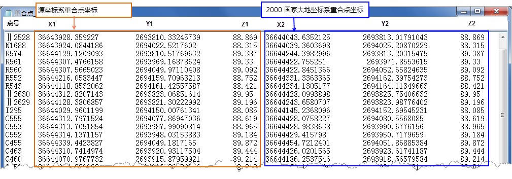
Figure: Common Points (.txt) File - Manual Input: Click the "Add Data" button in the common point settings toolbar to add a new record in the common points list box, where you can manually input the corresponding coordinates of the common points.
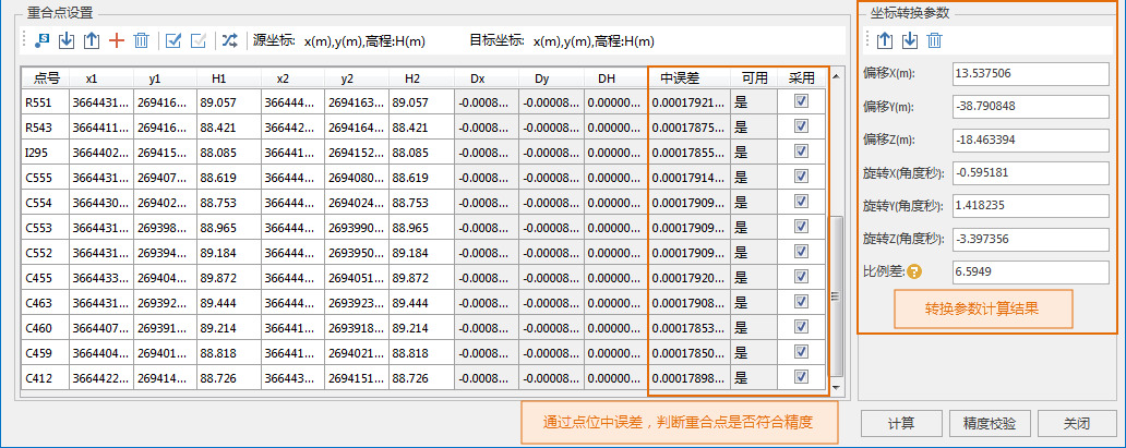
- After importing common points, you can view the details of the common points in the list box. By checking the checkbox in the Apply column, you can set which points participate in the calculation of coordinate transformation parameters. The number of control point pairs should not be less than 6 groups.
- Calculate Coordinate Transformation Parameters: Click the "Calculate" button to perform the calculation of coordinate transformation parameters. The following results are obtained:
① The program substitutes the common points into the transformation model and uses the least squares method to calculate the transformation parameters, including Offset X, Offset Y, Offset Z, Rotation X, Rotation Y, Rotation Z, and Scale Difference. The units for Offset X, Offset Y, and Offset Z are "meters"; the units for Rotation X, Rotation Y, and Rotation Z are "arcseconds"; and the scale difference is in parts per million (ppm).
② The coordinate residuals (Dx, Dy, DH) of the common points and the mean square error of the points are calculated. The program identifies common points with coordinate residuals greater than 3 times the mean square error of the points as unavailable points, indicated as No in the Usable column; otherwise, they meet the accuracy requirements.
To improve the accuracy of the transformation parameters, users can remove unavailable common points or set them as not used, and update the transformation parameters.
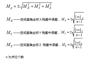
The relevant error calculation formulas are as follows:
- Common Point Residual (Dx, Dy, DH) = Converted Coordinate Value of Common Point - Known Coordinate Value of Common Point
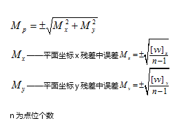
- Mean Square Error of Point Calculation Formula:
- Mean Square Error of Planar Point:
- Calibrate Precision: Click the calibrate precision button to open the calibrate precision dialog. Import common points that were not used in calculating the transformation parameters as external check points. The number of these points should be no less than 6 and uniformly distributed. Use internal符合 accuracy and external符合 accuracy assessment to evaluate the coordinate transformation accuracy based on the mean square error of the residuals of the common points used in calculating the transformation parameters. Points with residuals less than 3 times the mean square error of the points meet the accuracy requirements.
- Export Transformation Parameters: After calibrating precision合格, click the export button in the coordinate transformation parameters combo box to export the calculated transformation parameters as a projection transformation parameters file (*.ctp).
- Use the exported projection transformation parameters file (*.ctp) to project the entire dataset of the control point area. For information on reprojecting datasets, please see Reproject Dataset. Import the calculated transformation parameters in the "Parameter Settings" dialog to achieve projection of the entire dataset.
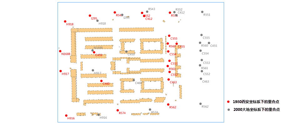
- The overlay display result of the converted data and the data before conversion is shown below:
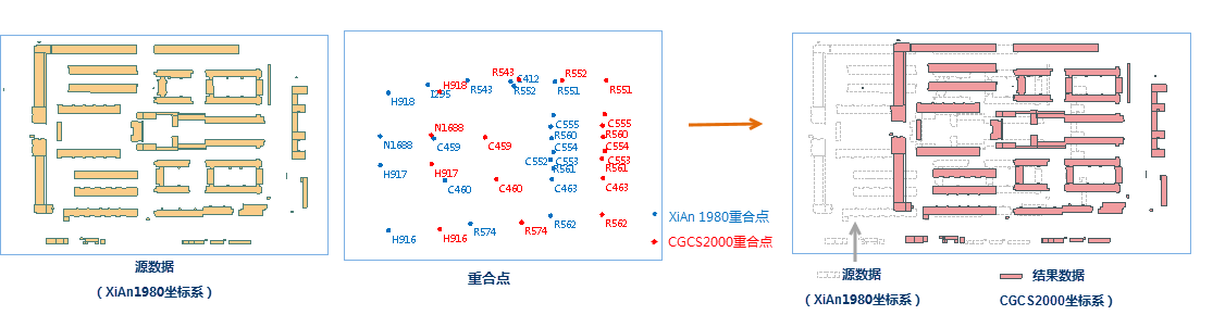
Figure: Data Comparison Before and After Conversion
Related Topics
Calculate Transformation Model Parameters