


Feature Description
Users can modify the parameters of a custom thematic map in the "Custom Thematic Map" window to achieve a more desirable thematic map effect.
In a custom thematic map, the fields displayed in the field drop-down list default to Field Alias. If needed, you can switch to the field name in the File tab -> Options group. For details, refer to the Preferences document.
Operation Steps
When creating custom thematic maps based on area layers, line layers, and point layers respectively, the settable content in the "Thematic Map" window varies slightly. Area layer thematic maps support "Fill" and "Line Style" settings, line layer thematic maps support "Line Style" settings, and point layer thematic maps support "Symbol" settings.
- Double-click a custom thematic map layer in the Layer Manager; the "Thematic Map" window displays the settings information of the selected custom thematic map.
- Thematic Map Layer: Displays the name of the currently displayed thematic map.
- Properties: The "Properties" item in the "Thematic Map" window is used to set the fill style, line style, and marker style of the thematic map. Fill style is valid for area objects in area vector thematic layers, line style is valid for line objects in line vector thematic layers and the edges of area objects in area vector thematic layers, and marker style is valid for point objects in point vector thematic layers.
Fill: Sets the rendering style of area objects in the area layer.
-
- Fill Style: Select a numeric field or expression to fill the object based on the value of this field or expression corresponding to the style with the same ID in the resource fill library. For example, after setting a fill style field, if the corresponding field value of an object is 8, the system will search the resource fill library for the fill style with ID 8 and use that style to render the object.
- Transparency: Select a numeric field or expression, the value of which represents the transparency of the corresponding object's fill style. For example, an object with a field value of 0 will have a completely opaque rendering style; an object with a field value of 100 will be completely transparent. Values less than 0 or greater than 100 are treated as completely opaque.
- Fill Foreground Color: Select a numeric field or expression, the value of which sets the fill foreground color. The default system reads color values in decimal under RGB Color Mode. For example, to set the fill foreground color to blue, whose hexadecimal value is #0003E8, convert that hexadecimal to decimal, which is 1000, then set the field value to 1000, and the map will display blue.
Note: If you do not know which decimal value corresponds to which color, you can use the Display Hexadecimal Value function to directly input hexadecimal color values in the attribute table.
- Fill Background Color: Select a numeric field or expression, the value of which sets the fill background color. The color settings are the same as for "Fill Foreground Color".
- Gradient Style: Select a numeric field or expression, the value of which determines the gradient mode of the fill style. If the field value is 1, a linear gradient is used; if 2, a circular gradient; if 3, a conical gradient; if 4, a square gradient; for any other value, no gradient is used.
- Gradient Angle: Select a numeric field or expression, the value of which sets the rotation angle of the gradient fill. The default value is 0 degrees. If the field value is greater than 0, it represents rotating counterclockwise by the corresponding angle; otherwise, rotating clockwise by the corresponding angle. The unit is 1 degree.
- Gradient Horizontal Offset: Select a numeric field or expression, the value of which sets the X offset (in percentage) of the gradient fill center relative to the fill extent center. It is only available for circular, conical, and square gradient modes. Positive values shift right, negative values shift left.
- Gradient Vertical Offset: Select a numeric field or expression, the value of which sets the Y offset (in percentage) of the gradient fill center relative to the fill extent center. It is only available for circular, conical, and square gradient modes. Positive values shift up, negative values shift down.
- Line Style: Sets the rendering style of line objects in line layers, or the edge rendering style of area objects in area layers.
- Line Style: Select a numeric field or expression, the value of which corresponds to a style in the resource line style library based on the ID to render the object. For example, after setting a line style field, if the corresponding field value of an object is 8, the system will search the resource line style library for the line style with code 8 and use that style to render the line object.
- Line Color: Select a numeric field or expression, the value of which sets the line color. The color settings are the same as for "Fill Foreground Color".
- Line Width: Select a numeric field or expression, the value of which sets the width of the selected line style. The unit is 0.1 mm.
- Symbol: Sets the rendering style of point objects in point layers.
- Marker Style: Select a numeric field or expression, the value of which corresponds to a style in the resource symbol library based on the ID to render the object. For example, after setting a marker style field, if the corresponding field value of an object is 8, the system will search the resource symbol library for the marker style with code 8 and use that style to render the point object.
- Symbol Color: Select a numeric field or expression, the value of which sets the point symbol color. The system first converts the field value to hexadecimal and then selects the corresponding color. The color settings are the same as for "Fill Foreground Color".
- Symbol Size: Select a numeric field or expression, the value of which sets the size of the selected symbol. The unit is 0.1 mm. Note: Setting to 0 means displaying at the original size; setting to a negative value means the symbol is not displayed.
- Symbol Width: Select a numeric field or expression, the value of which sets the width of the selected symbol.
- Symbol Height: Select a numeric field or expression, the value of which sets the height of the selected symbol.
 Notes:
Marker Size and Symbol Width/Height can only select one item; they are not cumulative. Once you set one, the setting of the other becomes invalid.
- Rotation: Select a numeric field or expression, the value of which sets the rotation angle of the point symbol. If the field value is greater than 0, it represents rotating counterclockwise by the corresponding angle; otherwise, rotating clockwise by the corresponding angle. The unit is degrees.
- RGB Vertex Color: Check this checkbox. The user-defined fill color, line style color, and color will be displayed according to the RGB vertex color by default. If unchecked, the colors will be displayed according to the BGR color value.
-
- Custom thematic maps created or modified by users can be saved as templates to be applied to thematic maps of other layers. For saving as a thematic map template, see: Save to Thematic Map Template Library.
- Field and expression values correspond to symbol library ID values. Taking the marker symbol library as an example: Open the workspace -> Symbol Library -> Fill Symbol Library. The method for checking the ID value is shown in the figure below:
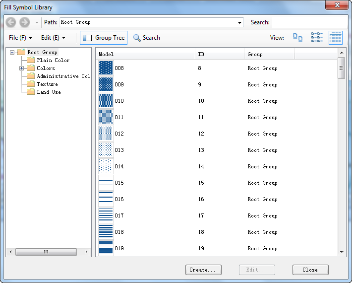
Marker Symbol Library ID Viewing Window
Related Topics