


Generate Tie Points
Feature Description
Tie points are homologous image points that can construct a stereo model or establish connections between adjacent models (images). Generate tie points helps provide accuracy during geometric correction to ensure spatial consistency of the images.
Function Entry
Satellite Image Processing tab->Geometric Correction group->Generate Tie Points.
Parameter Description
- Input Image Type: Select the image type for generating tie points. The default is Panchromatic Image. It can also be switched to Multispectral Image, Forward-Looking Image, Rear-View Image, or Front View and Rear View Image based on the specific image type.
- Refer to the Adjustment File: Based on existing adjustment file information, make the newly generated tie points closer to the accuracy of existing tie points. Use the Add and Delete buttons in the toolbar to conveniently manage multiple referenced adjustment files.
- Plane Accuracy: The image planar accuracy determines whether preprocessing is performed during tie point matching.
- Low: Generally indicates that the image planar accuracy error is greater than 40 pixels, requiring preprocessing.
- Height: Generally indicates that the image planar accuracy error is less than 15 pixels, without needing preprocessing.
- Medium: When the image accuracy cannot be determined, select this option, and the program will automatically estimate the accuracy.
- Error Threshold: Set the error threshold for removing outliers during image matching when generating tie points. The value range is [0,40], with a default of 5 and unit of px. A larger threshold retains more tie points but increases the probability of retaining erroneous points.
- Point Distribution Mode: Select the tie point distribution mode. Two modes are provided: Conventional and Uniform. The default is Conventional.
- Conventional: Divide each overlapping area into N*M sub-regions, then select n image blocks of size 512*512 from each sub-region for homologous point matching, ensuring stable and reliable homologous points. The generated tie points will cover the entire overlapping area as much as possible.
- Number of Blocks in Column Direction: The number of blocks each overlapping area is divided into in the column direction, with a default value of 4.
- Number of Blocks in Row Direction: The number of blocks each overlapping area is divided into in the row direction, with a default value of 4.
- Matching Method: The following six matching methods are provided. You can choose based on data characteristics and requirements. Among them, AFHORP and RIFT support multi-modal data matching; CASP and DEEPFT are based on deep learning, requiring additional AI model configuration and CUDA environment installation; in general, MOTIF, CASP, or DEEPFT are recommended.
- MOTIF (default): A template matching algorithm for multi-modal images, characterized by lightweight feature descriptors. MOTIF overcomes nonlinear radiometric distortions caused by differences between SAR and optical images.
- CASP: A novel cascaded matching pipeline that benefits from integrating high-level features, helping to reduce the computational cost of low-level feature extraction. The pipeline decomposes the matching stage into two progressive stages: first, establishing one-to-many correspondences at a coarser scale as cascaded priors, then using these priors for guidance to determine one-to-one matches at the target scale.[1]
- DEEPFT: A deep learning-based image matching method.
- SIFT: A method for extracting unique invariant features from images, enabling reliable matching between objects or scenes from different viewpoints.
- RIFT: A feature matching algorithm robust to large-scale nonlinear radiometric distortions. It improves the stability of feature detection and overcomes the limitations of gradient-based feature description.
- AFHORP: A feature matching algorithm for multi-modal images. AFHORP is highly resistant to radiometric distortions and contrast differences in multi-modal images, and performs excellently in addressing direction reversal and phase extreme mutation issues.
- Intra-Block Maximum: The maximum number of points retained within a block during image matching. The value range is [1,2048], with a default of 256.
- Uniform: The generated tie points will be evenly distributed in the overlapping area. The number of points is smaller than that of the conventional distribution, but the distribution is more uniform. It is suitable for cases with large internal distortions in the image.
- Number of Seed Points: Set the number of seed points for homologous point matching on each image. The value range is [64,6400], with a default of 512. When the image texture is poor, increase the number of tie points to ensure enough points are matched, improving the quality of subsequent imagery.
- Seed Point Search: Set the method for finding seed points. Two methods are provided: Grid Center Point and Corner Point. The default is Corner Point.
- Corner Point: Select points with prominent features in the region as seed points.
- Grid Center Point: Use the center point of the grid cell as a seed point; this search method is random.
- Template Size: Set the interval between seed points. The value range is [1,256], with a default of 40 and unit of px. A larger template makes the searched points more reliable but takes longer.
- Search Radius: Set the search radius for seed points during image matching. The value range is [0,256], with a default of 40 and unit of px. A larger search radius results in a larger matching range and longer processing time.
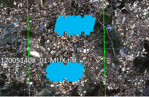
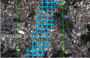
Figure: Regular distribution Figure: Uniform distribution - Conventional: Divide each overlapping area into N*M sub-regions, then select n image blocks of size 512*512 from each sub-region for homologous point matching, ensuring stable and reliable homologous points. The generated tie points will cover the entire overlapping area as much as possible.
- Semantic Culling of Non-Ground Points: Not checked by default. When checked, based on AI semantic technology, tie points in cloud areas and building areas are automatically removed.
- Cloud Area: This parameter is displayed after checking Semantic Culling of Non-Ground Points. It is checked by default, meaning tie points in cloud areas will be automatically removed based on the set dataset. If unchecked, tie points in cloud areas are retained. The dataset must contain an ImageName field, and the name must correspond to the current image to be processed.
- Building Area: This parameter is displayed after checking Semantic Culling of Non-Ground Points. It is checked by default, meaning building areas will be automatically identified and tie points in those areas will be removed. If unchecked, tie points in building areas are retained.
Related Topics
Generate Ground Control Points
References
[1] Chen, P., Yu, L., Wan, Y., Pei, Y., Liu, X., Yao, Y., ... & Zhang, Y. (2025). CasP: Improving Semi-Dense Feature Matching Pipeline Leveraging Cascaded Correspondence Priors for Guidance. In Proceedings of the IEEE/CVF International Conference on Computer Vision (pp. 28063-28072).