


Feature Description
A ground control point (GCP) is a control point located at a specific position and target on an image, with coordinate information in the mapping coordinate system. Due to its high-precision spatial coordinate data, it can be used in processes such as geometric correction of remote sensing imagery, positioning accuracy verification, and spatial registration to achieve high-precision geographic reference and position tracking of image data.
Feature Entry
Satellite image processing tab ->Geometric Correction group ->generate ground control points.
Parameter Description
- Input image type: Select the type of image involved in generating control points. The default is Panchromatic Image. It can also be switched to Multispectral Image, Forward-looking image, Rear-view image, or Front view and rear view image according to the specific image type.
- Plane Accuracy: The image plane accuracy determines whether preprocessing is performed during control point matching.
- Low: Generally means the image plane accuracy error is greater than 40 pixels, requiring preprocessing.
- Height: Generally means the image plane accuracy error is less than 15 pixels, and no preprocessing is needed.
- Medium: When the image accuracy cannot be determined, select this option, and the program will automatically estimate the accuracy.
- Error Threshold: Set the error threshold for eliminating gross errors in image matching. The value range is [0,40], the default is 5, and the unit is px. The larger the threshold, the more control points are saved, but it increases the possibility of saving erroneous points.
- Point distribution mode: Select the point distribution pattern, providing two modes: Conventional and Uniform.
- Conventional: Divide each scene into N*M sub-regions, then select n image blocks of size 512*512 from each sub-region for control point generation. The generated ground control points will cover the entire image as much as possible.
- Number of blocks in column direction: The number of blocks divided in the column direction for each scene image, default value is 4.
- Number of blocks in row direction: The number of blocks divided in the row direction for each scene image, default value is 4.
- Matching method: The following six matching methods are provided, which can be selected based on data characteristics and requirements. Among them, AFHORP and RIFT support multimodal data matching; CASP and DEEPFT are based on deep learning, requiring additional AI model configuration and CUDA environment installation; in general, MOTIF, CASP, or DEEPFT is recommended.
- MOTIF (default): A template matching algorithm for multimodal images, characterized by lightweight feature descriptors. MOTIF can overcome nonlinear radiation distortions caused by differences between SAR and optical images.
- CASP: A novel cascade matching process that benefits from integrating high-level features, helping to reduce the computational cost of low-level feature extraction. The process decomposes the matching stage into two progressive stages: first, one-to-many correspondences are established at a coarser scale as cascade priors; then, these priors are used to guide the one-to-one matching at the target scale.[1]
- DEEPFT: A deep learning-based image matching method.
- SIFT: A method for extracting distinctive invariant features from images, which can be used for reliable matching between objects or scenes under different viewpoints.
- RIFT: A feature matching algorithm robust to large-scale nonlinear radiation distortions. It improves the stability of feature detection and overcomes the limitations of gradient-based feature description.
- AFHORP: A feature matching algorithm for multimodal images. AFHORP has strong resistance to radiation distortions and contrast differences in multimodal images, and performs well in solving problems of direction reversal and phase extremum mutation.
- Intra-block maximum: The maximum number of points retained within a block during image matching. The value range is [1,2048], and the default is 256.
- Uniform: The generated tie points will be evenly distributed in the overlapping area. The number of points is less than that of the conventional distribution, but the distribution is more even, suitable for cases with large internal distortions in the image.
- Number of seed points: Set the number of seed points for matching homologous points on each scene image. The value range is [64,6400], and the default is 512. When the image texture is poor, the number of control points needs to be increased to ensure enough points are matched, improving subsequent image quality.
- Seed point search: Set the method for finding seed points. Two methods are provided: Raster center point and Corner point, the default is Corner point.
- Corner point: Points with obvious features within the selected region are used as seed points.
- Raster center point: The center point of the raster is used as the seed point, and this search method is random.
- Template size: Set the interval size between seed points. The value range is [1,256], the default is 40, and the unit is px. The larger the template, the more reliable the searched points, but the longer the time.
- Search radius: Set the search radius of seed points for image matching. The value range is [0,256], the default value is 40, and the unit is px. The larger the search radius, the larger the matching range and the longer the time.
- Conventional: Divide each scene into N*M sub-regions, then select n image blocks of size 512*512 from each sub-region for control point generation. The generated ground control points will cover the entire image as much as possible.
- Semantic culling of non-ground points: Based on AI semantic technology, automatically eliminate control points in cloud areas and building areas.
- Cloud Area: This parameter is displayed after checking Semantic culling of non-ground points. Checked by default, meaning the control points in the cloud area will be automatically eliminated based on the set dataset. If unchecked, the control points in the cloud area will be retained. The dataset must contain an ImageName field, and the name must correspond to the current image to be processed.
- Building Area: This parameter is displayed after checking Semantic culling of non-ground points. Checked by default, meaning the building area will be automatically identified and the control points in that area will be eliminated. If unchecked, the control points in the building area will be retained.
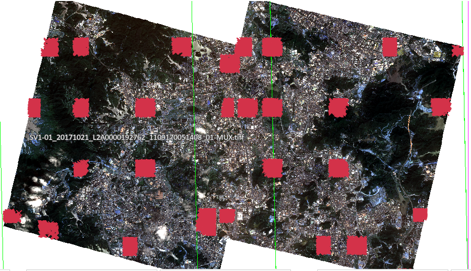 |
| Figure: Automatically generated ground control points |
Related Topics
References
[1] Chen, P., Yu, L., Wan, Y., Pei, Y., Liu, X., Yao, Y., ... & Zhang, Y. (2025). CasP: Improving Semi-Dense Feature Matching Pipeline Leveraging Cascaded Correspondence Priors for Guidance. In Proceedings of the IEEE/CVF International Conference on Computer Vision (pp. 28063-28072).