


Viewing feature object properties is crucial in practical applications. It serves not only as the foundation for ensuring safety and accuracy in ship navigation, but also as a critical step in guaranteeing the precision of chart production processes and correct symbolization. For example:
- When assisting ship navigation, viewing attributes such as light intensity and flashing frequency of lighthouses can help ships navigate safely at night or under low visibility conditions. During route planning, by examining chart elements' related information and reference objects like channel boundaries, shoals, and other potential hazards, ships can avoid dangerous areas and ensure safe navigation paths.
- In chart production, cartographers can verify data accuracy by inspecting feature object properties to ensure attribute values (such as water depth, lighthouse light characteristics, channel boundaries, etc.) match real-world conditions, thereby generating precise charts. To ensure proper chart symbology, cartographers can validate correct symbolization and presentation of features through examining object properties, enabling mariners to accurately interpret chart information.
SuperMap iDesktopX supports viewing catalog information of chart data feature objects, including attributes, related information, connective tissue, reference objects, and nodes.
Supported data types comply with the following standards:
- S-101 Electronic Chart
- S-127 Maritime Traffic Management
- S-131 Port Infrastructure
Steps
Select Feature Objects
Accurate selection of feature objects forms the basis for viewing properties and operations. Precise selection can be achieved through click-selection or rectangle-selection, supplemented by the select object function for result filtering.
- Toggle Selection State
- Right-click toggle: Right-click on the map to enter selection mode.
- Toolbar toggle: Click the Select button in the Browse group under the Maps Tab.
- Common Selection Methods
- Click-selection: Single-click to select individual objects; hold Shift for multiple selections.
- Rectangle-selection: Hold left mouse button to create a rectangular area; objects with centroids within the selected region will be selected upon release. Hold Shift for cumulative selection.
- Select Object
- Preliminary filtering: Right-click the map to filter from the first 20 selected objects, with highlighting for easy identification.
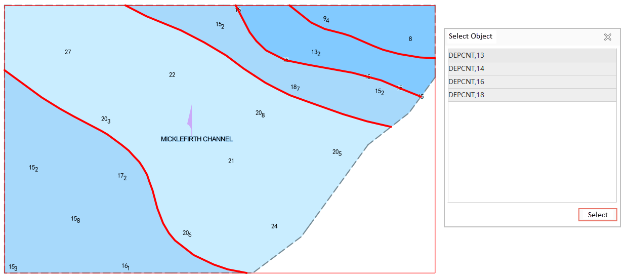
- Batch filtering: When exceeding 20 selected objects, click "more..." to open the Select Object dialog. Batch selection can be performed by feature names, with real-time highlighting updates.
The selection effect is shown in the following figure:
View Feature Object Properties
- Under the Maps Tab, click Select to enter selection mode. Select objects in the chart window using Shift key or drag-selection for multiple selections.
- Right-click in the chart window and choose Properties from the context menu.
- The pop-up Properties window displays details of selected features. Switch between Attributes, Related Information, Connective Tissue, Reference Object, and Node tabs to view corresponding content. Note: Related Information, Referenced Object, and Reference Object tabs only appear when objects contain these properties.
Parameter Description
Properties
Defines which attributes can be bound to specific feature types and their possible value ranges. For example, the "Light Color" attribute might only permit "Red", "Green", or "White".
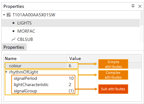
- Simple attributes: Feature attributes without sub-attributes. E.g., the "colour" attribute shown below.
- Complex attributes: Feature attributes containing sub-attributes. E.g., the "rhythmOfLight" attribute shown below includes "signalPeriod", "lightCharacteristic", and "signalGroup" sub-attributes. Sub-attributes of complex attributes can also be simple or complex.
Related Information
Defines relationships between different feature types, helping describe complex geographic entities and their interactions in electronic charts.
In S-127, features can be systematically associated with relevant nautical information, contact details, supervisory management, and reporting requirements, typically including these information types:
- General characteristics: Nautical Information, Regulations, Restrictions, and Recommendations, providing annotations, rules, limitations, or suggestions.
- Source-related characteristics: Organisation Contact Area, Contact Details, offering organizational contact information.
- Organization-supervised characteristics: Supervised Area, Authority, etc.
- Reporting-related characteristics: Reportable Service Area, Ship Report, etc.
During feature queries, the Related Information section in the right Properties panel displays all related information and information types. Select desired information to view detailed attributes in the lower panel. For incomplete text values (like long text shown below), hover over the text to view full content in tooltip.
Connective Tissue
Displays feature types associated with the object and shows connective tissue attributes.
- Connective tissue enhances precise map positioning by describing spatial and compositional relationships between features, particularly valuable in complex geographic scenarios. Widely used in chart data platforms to ensure navigation accuracy and map information practicality. Examples:
- When determining lighthouse positions, associated fairways or navigation marks help quickly locate relevant elements.
- During submarine cable laying or drilling operations, associated seabed topography and obstacles aid precise area positioning.
- During queries, the Connective Tissue section displays all related tissues. Clicking features auto-centers map view with highlighting, and shows attributes in lower panel.Reference Object
In chart data, graphical features often consist of multiple geometric components (point-chain structures), collectively called "reference objects". When selecting a feature, its "reference object" properties record underlying geometry information, defined and controlled by:
- Object ID: Unique identifier for each reference object.
-
Boundary Direction: Reference direction for linear spatial objects, including Forward (consistent with node order), Reverse (opposite to node order), and Direction Independent.
-
Boundary Type: Reference edge type, either Outer Border or Internal Border.
- Mask Type: Controls reference object display in symbolic representation:
- Shield: Hides overlapping display elements (e.g., adjacent fairway edges)
- Show: Explicitly displays elements
- Nothing to do with mask: No masking effect
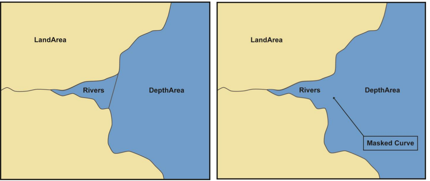
For example, the left figure shows a river composed of multiple polygon objects. Setting mask type to Shield at adjacent boundaries (right figure) hides dividing lines.
Node
- Contains completely within type, total sub-objects, current sub-object, total nodes, node coordinates, etc.
Related Topics