


Instructions for use
SuperMap supports topology construction and inspection of editable Chart Groups (S-57, CJ-57) to ensure the accuracy and consistency of Chart Data.
In the S-57 Chart Data model, objects are divided into two categories:
- Feature Object: Non-Position Info describing a real-world entity, with attribute data but no Geometry Info, relying on spatial objects to determine geometry and position.
- Spatial Object: It contains the geometric Position Info of the real-world entity, and may have attribute data to describe the spatial position characteristics of the entity.
The feature object determines its geometry and position through its relationship with the spatial object, and this dependence forms the Topology of the chart. According to the Electronic Chart (ENC) product specification, the Topology at the chain node level must be established for the space object. SuperMap supports the topological structure of chain node level, and the space object mainly includes three types:
- Isolated node
- Connect the nodes
- Edge
Each edge must start and end at a connecting node. Closed edges use the same connection node. The reference rules of the characteristic object are as follows:
- Dot Feature Object: Reference isolated node or connection node
- Line and Area Feature Objects: Connect nodes and edges by reference
Topology Check
Topology Check is used to verify whether the Topology of Chart Data meets the specifications, ensuring the integrity and consistency of the data. The main inspection contents include:
- Identifier Uniqueness Check: Verify the uniqueness of all FOIDs, RCIDs, and RCIDs of spatial lines, connecting nodes, and isolated nodes.
- Reference correctness check: check whether all space lines correctly reference space point objects and are referenced by feature object objects, whether all connection nodes are referenced by space lines, and whether all isolated nodes are referenced by point feature object objects.
- Geometry and Position Accuracy Check: Make sure that all the point, line, and surface feature object objects can find the space object object and the coordinates are correct.
- Other rule validation: such as correctness of orientation, usage, and mask.
The operation steps are as follows:
- In the Chart Data editing mode, enter the Chart tab-> Data Check and Topology group-> click the Topologically Check and Build button.
- On the Topology Check dialog that appears, set the Datasource and Editable Chart Group to be checked.
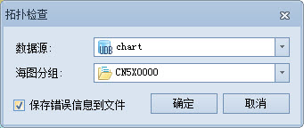
- By default, the Save error messages to a file option is selected to save Errors as an XML file.
- Click the OK button to execute the Topology Check. The Check Result is displayed in the Output Window, including the number of errors and the ErrorsSave path.
Build Topological Relationship
After modifying Chart Data or producing new Chart Data, Build Topological Relationships again to ensure the logical consistency of data. The process involves the creation of a spatial target object and the reference information of the feature target to the spatial target.
The operation steps are as follows:
- Perform the Topology Check described above first.
- If a Topology error is detected, the system will pop up the Build Topological Relationship prompt Do you want to build a topology?.
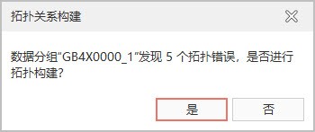
- Click the OK button, the system will delete the original Topology and rebuild it, and the construction progress bar dialog box will pop up at the same time.
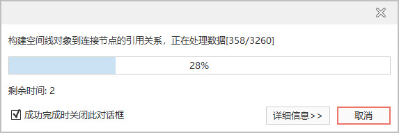
- When the run is complete, the Output Window prompts you to build the results.
Related topics