


Instructions for use
When there are multiple routes from the start point to the end point, it finds the point or arc segment through which all routes must pass.
In order to ensure the connectivity of the two points, the necessary points and lines can be obtained through the key element query. If the queried points and lines can be guaranteed to be unobstructed, the two points can be guaranteed to be connected. In the pipeline network, it is mainly used to monitor the leakage points of key lines to ensure the safety and connectivity of the pipeline network; in the road network, it can monitor the smooth situation of key roads to ensure the smooth of the necessary points and lines, which can ensure the smooth between two points.
Operation steps
- Opens the network layer in the current Map.
- Before proceeding with Network Analysis, you need to set up the Network Analysis environment. On the Spatial Analysis tab, in the Facility Network Analysis group, select the Environment Settings "check box to display the Environment Settings" Dock Bars. In this window, set the weight field, node/Edge ID Field, Enable Rules, and steering table of Network Analysis. For an introduction to the Environment Settings window, see Network AnalysisEn vironment Settings window Page.
- On the Spatial Analysis tab, in the Facility Network Analysis group, click the Network Analysis Drop-down Button. Select the Critical Element Analysis item in the drop-down menu that pops up to create an instance of Critical Element Analysis. For an introduction to instance windows, see Introduction to Instance Management window Pages.
- In the current network layer, click to select a Start Node to add. There are two ways to add a Start Node. One is to click the mouse on the Network Data layer to complete the addition of the Start Node; One is to import the point objects in the Point Dataset as sites. For details, see the Add Site dialog box. The adding method of
- End Node is the same as that of Start Node. You can add End Node by referring to the adding method of Start Node. Click The Parameter Settings "button
- in the Network Analysis Instance Management window to pop up the Critical Element Analysis" dialog box. Set the Analysis Parameters. The Analyst Result type can be set
in the Critical Element Analysis Settings dialog box:
Critical Node: Find the necessary node element between Start Node and End Node.
Critical Edge: Find the necessary arc feature between the Start Node and the End Node.
WhenParameter Settings is complete, click OK to exit the Critical Element Analysis Settings dialog box.
When - all Parameter Settings are complete, Click the Execute button in the Facility Network Analysis group on the Spatial Analysis tab or click the Execute button in the Instance Management "window, and you can set the parameters. Perform a Critical Element Analysis operation. After
- The execution completed, the Analyst Result will be automatically displayed Add to Current Map. At the same time, the Output Window will prompt that the execution of Critical Element Analysis is successful, and the elapsed time is * * * seconds. Analyst Result is shown in the figure below. The red dot is the found Critical Node, and the green line is the found Critical Edge.
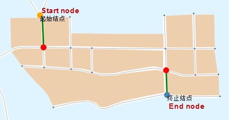
Figure: Critical Element Analysis result
 Related topics