


Deformation Detection
Feature Description
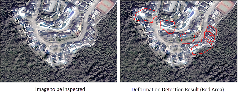
Deformation detection identifies distorted areas such as mountains, roads, and buildings in images after orthorectification or fusion. This method simplifies manual inspection workflows and significantly improves detection efficiency. Based on detection results, users can quickly locate distorted areas and perform image restoration to enhance final output quality.
SuperMap ImageX Pro 11i(2024) version starts to support this feature.
Feature Entry
Imagery Tab->Quality Assessment Group->Deformation Detection.
Parameter Description
- Detection Type: Provides three detection types: Terrain Deformation, Road Deformation, and Building Deformation, all selected by default. Users can choose one or two types according to project requirements.
- Image to be checked: Supports input of orthorectified images, true color images, and fused images. When the image path contains both panchromatic and multispectral images, only the panchromatic image is loaded.
- Add Image: Supports four methods: Add File, Add Folder, Add List, and Add Mosaic Dataset to configure images for deformation detection.
- Add RPC File: If the image is produced by SuperMap products, no RPC file input is required. For images from other software, the adjusted RPC file must be imported.
- Elevation Data: Sets DEM elevation data for detecting distorted areas. Recommended to use DEM data with 30m or higher resolution. Supports Tiff/GeoTIFF, Erdas Image, PCIDSK, and ArcInfoGrid formats. ArcInfoGrid data can only be loaded via Add Folder.
- Detection Range:
- Range Data: Sets polygon data for detection range. Supported formats: UDBX/UDB, GeoJson, ShapeFile.
- Terrain Deformation:
- Deformation Threshold: Marks areas as distorted when deformation exceeds this value. Default: 0.4, valid range (0.15,1.0). Lower values increase false positives; higher values improve precision but may cause missed detections.
- Road Deformation:
- Road Line Data: Sets road line data. Supported formats: UDBX/UDB, GeoJson, ShapeFile.
- Sampling Interval: Samples road lines for deformation analysis. Default: 15 meters.
- Deformation Threshold: Marks areas as distorted when deformation exceeds this value. Default: 0.2, valid range (0,1.0).
- Road Buffer Radius: Sets buffer radius for result regions. Larger values make results more prominent. Default: 3 meters.
- Building Deformation:
- Building Area: Sets polygon data for building areas. Supported formats: UDBX/UDB, GeoJson, ShapeFile. If not set, AI models will automatically detect building areas with longer processing time.
- Deformation Threshold: Marks areas as distorted when deformation exceeds this value. Default: 0.5, valid range (0.4,1.0).
- Pixel Count Threshold: Retains detection results when distorted areas have pixels ≥ this value. Default: 20.
-
- Datasource: Specifies the datasource for storing results. Result dataset names are fixed as MountainDeformation, RoadDeformation, and BuildingDeformation.
Related Topics