


Definition of Projection
The surface of the Earth's ellipsoid is curved, while maps are typically drawn on flat paper. Therefore, when creating maps, the curved surface must first be flattened. However, a spherical surface is non-developable; directly flattening it would cause ruptures or wrinkles. Using such a ruptured or wrinkled plane for mapping is impractical, so special methods are required to unfold the surface into a rupture-free and wrinkle-free plane, thus giving rise to the theory of map projection.
The fundamental principle is: since a point's position on the sphere is represented using latitude and longitude, during projection, the intersections of certain longitude and latitude lines are first plotted on a plane. Points with the same longitude are then connected to form meridians, and points with the same latitude are connected to form parallels, creating a graticule. With this graticule, points on the sphere can be plotted on the plane at corresponding positions based on their latitude and longitude, as shown below:
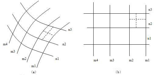 |
| Figure: Transferring Points on the Sphere to a Plane Based on Latitude and Longitude |
Essence of Projection
Many analytical techniques and spatial data are designed for two-dimensional or planar coordinates, requiring spatial coordinates to be stored via planar map projections. Thus, we often need to use map projections to convert three-dimensional gcs into two-dimensional planar coordinates. Map projection refers to transforming geographic coordinates (λ, φ) into planar coordinates (X, Y) through specific mathematical equations. Distortion inevitably occurs when transforming from three-dimensional to two-dimensional coordinates, and map projection minimizes this distortion.
The use of map projection ensures that geo maintains regional connections and integrity after transformation from gcs to planar coordinates. This is a fundamental requirement of cartography and a basic prerequisite for spatial operations and spatial analysis, making map projection crucial for applying geographic data in GIS.
Methods of Projection
There are two projection methods: geometric perspective and mathematical analytical methods.
The geometric perspective method utilizes perspective relationships between objects to project points from the Earth's surface onto a projection surface. For example, using planes, cylindrical surfaces, or conical surfaces as projection planes to transfer the curved surface (Earth's ellipsoid) onto a flat map, as illustrated below:
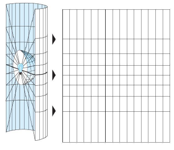 |
| Figure: Schematic Diagram of Perspective Projection Method |
The mathematical analytical method establishes a correspondence between the graticule on the Earth's ellipsoid and its counterpart on a plane. Essentially, it directly defines the functional relationship between the gcs of a point on the sphere and the Cartesian coordinates of its corresponding point on the plane. Most map projections today employ this method.
- Geometric Perspective Method
- Mathematical Analytical Method
Projection Distortion
The Earth's ellipsoid is a non-developable surface, while a map is planar. Flattening such a spherical surface inevitably causes ruptures or overlaps in certain areas, disrupting the continuity and completeness of features and topography there. For practical applications, ruptured or overlapped sections must be uniformly stretched or compressed to eliminate cracks and wrinkles. During this process, these map sections lose similarity to their counterparts on the Earth, resulting in distortion caused by projection. This alteration in the geometric properties of the graticule during projection from sphere to plane is termed map projection distortion.
Map distortions include length distortion, angular distortion, area distortion, and shape distortion.
Length distortion is the difference between the length ratio and 1, where the length ratio is the ratio of a tiny line segment on the projection plane to the corresponding segment on the ellipsoid. It reflects the degree of change in line segments post-projection and is the fundamental distortion in all projections, causing area and angular distortions.
Angular distortion is the difference between an angle formed by any two direction lines on the projection plane and the corresponding angle on the ellipsoid. It is a specific indicator of shape distortion.
Area distortion is the difference between the area ratio and 1, where the area ratio is the ratio of a tiny area on the projection plane to the corresponding area on the ellipsoid. It quantifies the degree of map projection distortion.
Shape distortion refers to the dissimilarity between contour shapes on the map and corresponding ground contours.
- Length Distortion
- Angular Distortion
- Area Distortion
- Shape Distortion
Related Topics
Description of Reference System Conversion Methods