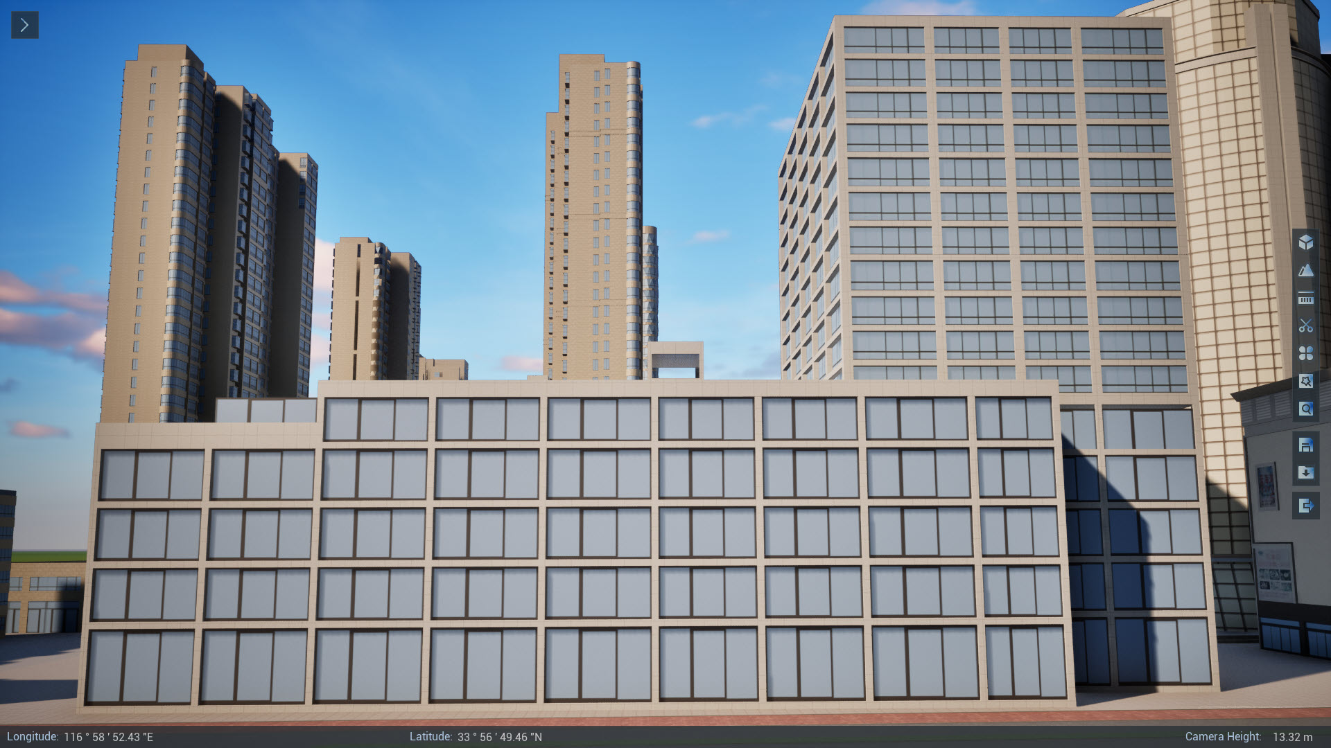
This page provides a way to make PBR materials based on the texture of the data itself, so as to achieve a beautiful effect. This method is suitable for beautification on the basis of preserving the color or texture of the data itself. This page illustrates the window effect as an example. The effect comparison diagram is shown in the following figure.
 |
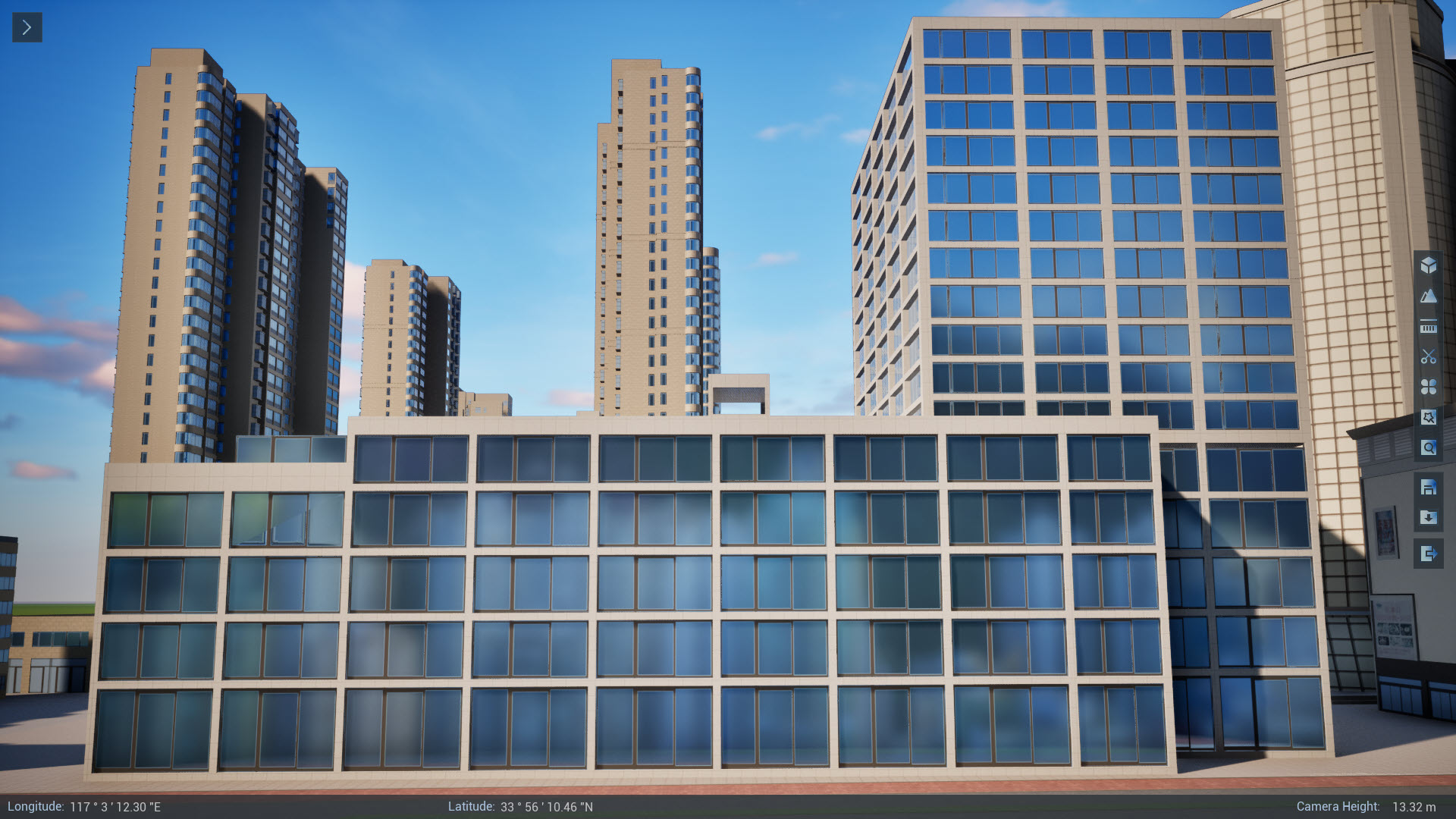 |
| original effect | beautification effect |
Get the original primary color texture
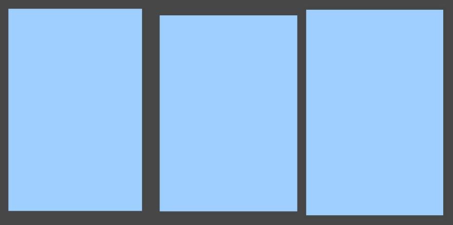
Original base color texture is the texture that comes with the data. If you have original modeling data obtained through 3ds Max, Revit and other software, you can obtain it directly. If you only have UDB data, you can obtain model materials in batches through SuperMap iDesktopX's Model Material Extraction function.
Make a metallic roughness map
This procedure uses PhotoShop as an example to illustrate how to make a metallic roughness map based on the original primary color texture obtained in the previous step.
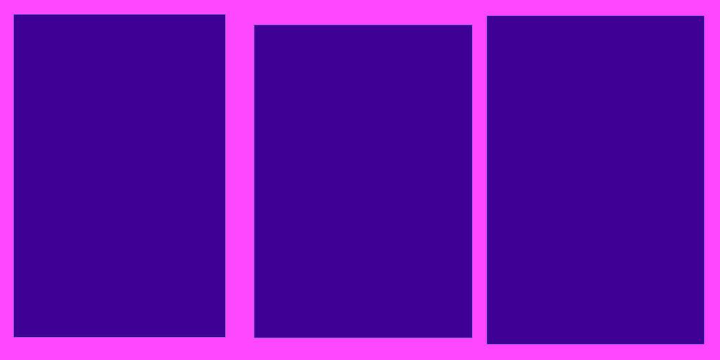
- First agree on the relevant expressions:
- The Red channel in the texture is used to express Metallicity. The whiter the metal, the stronger the metal, while the darker the metal, the weaker the metal.
- The Green channel in the texture is used to express Roughness. The whiter the rougher, the darker the smoother.
- When working with red and green channels, set the window frame portion to white and the glass portion to grayish black. The blue channel here is not needed and can be temporarily ignored.
- After processing, export the processed texture.
Making Normal Maps
There is no unique way to make normal maps. Here are some common methods.
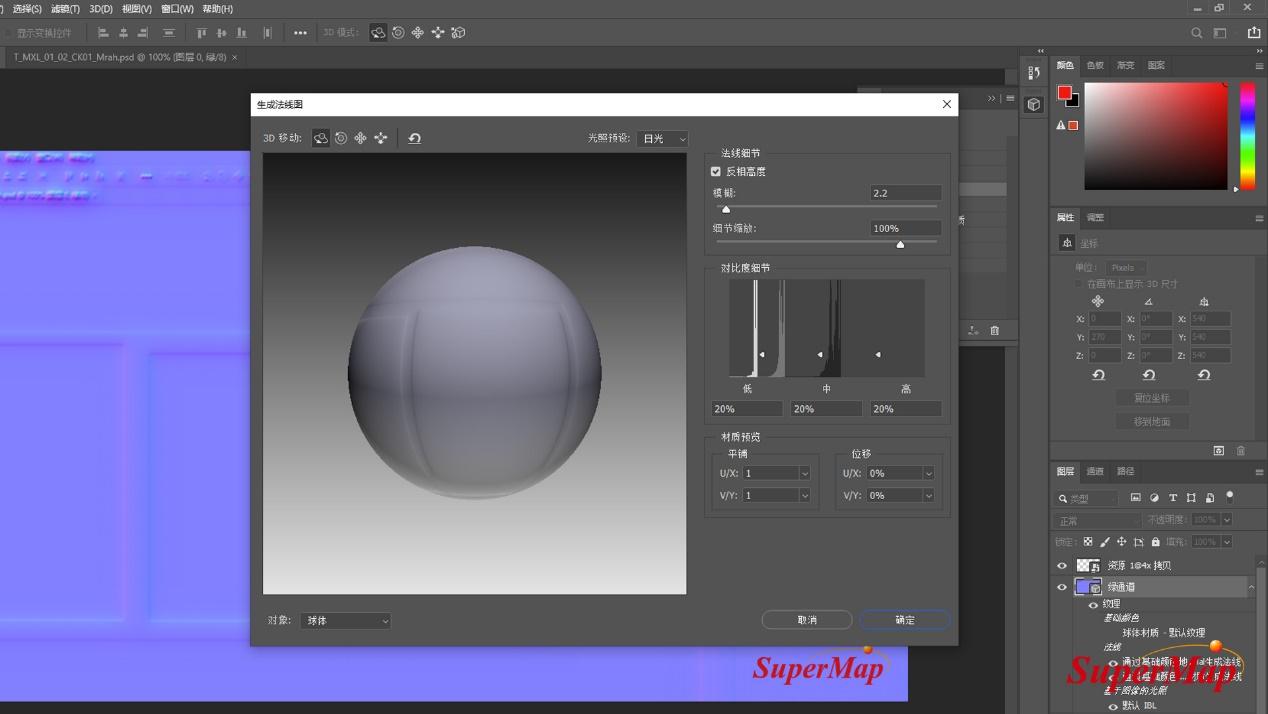 |
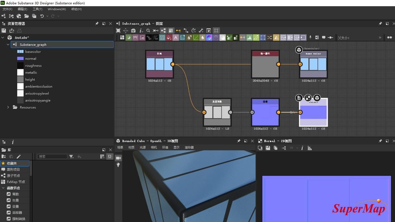 |
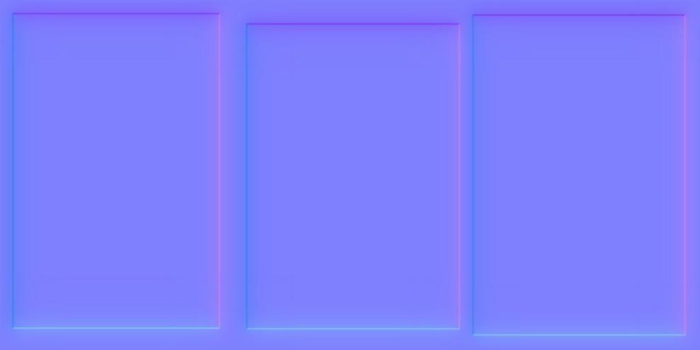 |
| Method 1 | Method 2 | normal map |
- Method 1: Make it by PhotoShop software's "Filter-3D-Generate Normal Map" command. This method is simple, but the effect of normal mapping is sometimes not obvious.
- Method 2: A common method used in the gaming industry is to make normal maps through Adobe Substance 3D Designer.
- Method 3: Use other tools such as CrazyBump to generate normal maps.
New Material
This step is to create a new material in Unreal Engine and connect the texture obtained in the above step to the corresponding channel.
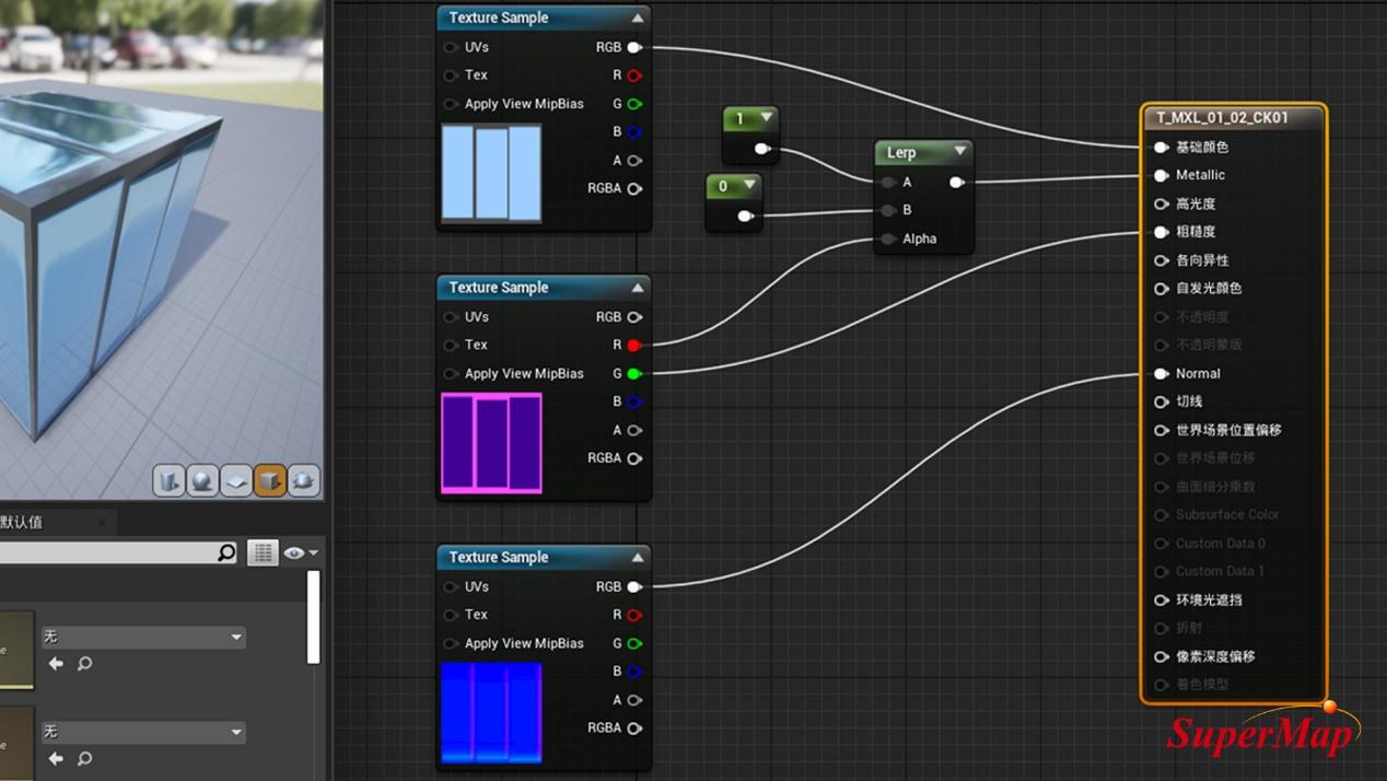
- Create a new material named T_MXL_01_02_CK01 in the Content Browser/All/Plugins/SuperMap Content/Materials/UE5 folder and open the Material Blueprint.
- First connect the RGB node on the right side of the original primary texture map to the base color node on the left side of the T_MXL_01_02_CK01 material.
- Then connect the R node on the right side of the Metallicity texture map to the Metallic node on the left side of the T_MXL_01_02_CK01 material. To create an artistic effect of glass reflections, add the Lerp function and connect the R node on the right side of the Metallicity texture map to the Alpha node on the left side of the Lerp function, and connect the A node on the right side of the Lerp function to the Metallic node on the left side of the T_MXL_01_02_CK01 material.
- Then connect the G node on the right side of the Metallic Roughness texture map to the Roughness node on the left side of the T_MXL_01_02_CK01 material.
- Finally, connect the RGB node on the right side of the normal texture map to the Normal node on the left side of the T_MXL_01_02_CK01 material.
Add Material Function
This step is to add a material function that reverses along the Y axis before the original texture, thus avoiding the problem of the texture flipping up and down after the material replacement.
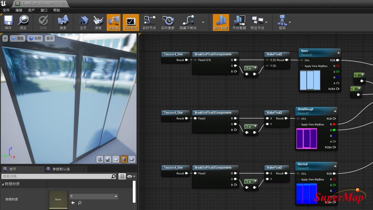
- Open the Content Browser/All/Plugins/SuperMap Content/Materials/MaterialFunctions folder, locate the SM_Texcoord_One material function, and drag it into the T_MXL_01_02_CK01 material blueprint generated in the previous section.
- In the Material Blueprint, right-click and add BreakOutFloat3Components, 1-x, MakeFloat2 material functions.
- Connect the material functions in the following order:
- The Result node to the right of Texcoord_One connects to Float3 (V3) to the left of BreakOutFloat3Components.
- The R node on the right side of BreakOutFloat3Components connects to the X(S) node on the left side of MakeFloat2, and the G node on the right side of BreakOutFloat3Components connects to the 1-x node on the left side.
- The node on the right side of 1-x is connected to the Y(S) node on the left side of MakeFloat2.
- The Result node to the right of MakeFloat2 connects to the UVs node to the right of the original primary color texture.
- Follow the steps above in this section to do the same before Metallicity Texture Map and Normal Texture Map.
- At this point, the material production is complete.
New Material Instance
If there are multiple materials in the scene that need to do this, this section provides a material instance method to reduce Unreal Engine editing of materials and optimize performance.
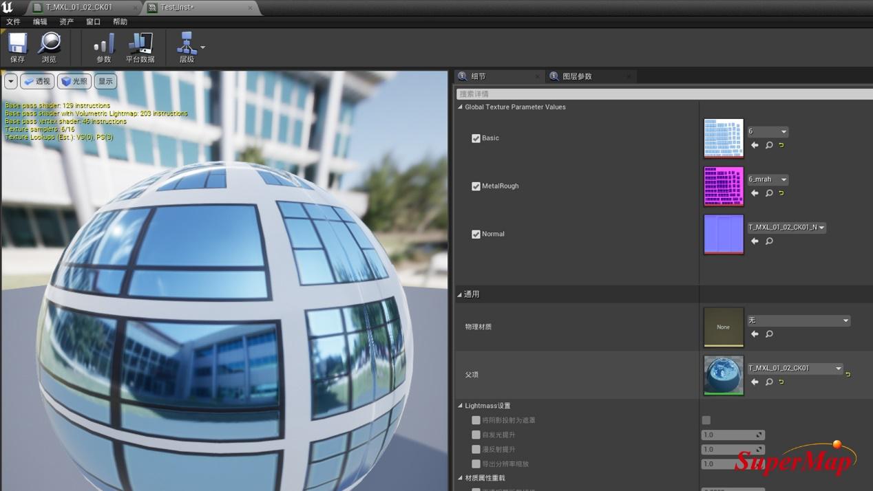
- Select the texture map in turn and click the right mouse button. Select Convert to Parameters from the pop-up right-click menu, and name the original base color texture, metallic roughness texture and normal texture parameters Basic, MetalRough and Normal respectively.
- Select the original T_MXL_01_02_CK01 material in the Content Browser and right-click. Select Create Material Instance from the pop-up right-click menu and name it Text_Inst.
- Open the material instance created in the previous step, check Basic, MetalRough, Normal in the details panel, and select the corresponding new texture through the drop-down menu after the corresponding parameter to replace it.
- More new materials can be processed as new material instances.
Replace Material
This part is mainly to replace the material made on the S3M tile.

- Using SuperMap iDesktopX's Generate Scene Tiles feature, the data is generated into S3M tile data. When generating tile data, the material type needs to select UE material, and other parameters can be configured according to needs.
- Add the S3M tile data generated in the previous step via the SuperMap editor controlin Unreal Engine.
- Run the current level and replace the material of the S3M tile data with the previously made material through the material replacement function. The effect after beautification can be obtained.


