


Instructions for Use
The Standard Map Frame function adds standard map sheet frame data to maps and saves results as CAD datasets in specified datasources. This tool enables quick creation of various maps based on national basic scales to enhance cartographic professionalism. It incorporates national basic geographic data (residential areas, water systems, land use, contours, administrative divisions) sharing the same coordinate system into standard sheets, along with slope scales, adjacent charts, and drafting information, facilitating rapid production of comprehensive standard maps.
This function complies with the latest national standard "GBT 13989-2012 National Basic Scale Topographic Map Subdivision and Numbering", applicable for 1:1,000,000 to 1:500 scale topographic maps.
Fundamentals of Topographic Map Subdivision
Chinese topographic map scales include: 1:1,000,000, 1:500,000, 1:250,000, 1:100,000, 1:50,000, 1:25,000, 1:10,000, 1:5,000, 1:2,000, 1:1,000, 1:500. These scales are grouped into four categories:
- Group 1: 1:1,000,000, 1:500,000, 1:250,000
- Group 2: 1:100,000, 1:50,000, 1:25,000
- Group 3: 1:10,000, 1:5,000
- Group 4: 1:2,000, 1:1,000, 1:500
Scales 1:500, 1:1,000, and 1:2,000 are classified as large-scale, others as medium/small-scale.
1:1,000,000 maps follow international subdivision standards with 6° longitude × 4° latitude per sheet. Smaller scales (1:500,000-1:5,000) subdivide parent sheets using specified longitude/latitude differences. For example, each 1:1,000,000 sheet divides into 2×2 (4) 1:500,000 sheets with 3°×2° coverage. This hierarchical subdivision continues through all scales.
1:2,000-1:500 scales may use either geographic subdivision or rectangular tiling (50cm×50cm or 40cm×50cm). The table below shows map ranges and row/column relationships for various scales:
| Scale | 1:1,000,000 | 1:500,000 | 1:250,000 | 1:100,000 | 1:50,000 | 1:25,000 | 1:10,000 | 1:5,000 | 1:2,000 | 1:1,000 | 1:500 | |
| Map Range | Longitude Diff. | 6° | 3° | 1°30′ | 30′ | 15′ | 7′30″ | 3′45″ | 1′52.5″ | 37.5″ | 18.75″ | 9.375″ |
| Latitude Diff. | 4° | 2° | 1° | 20′ | 10′ | 5′ | 2′30″ | 1′15″ | 25″ | 12.5″ | 6.25″ | |
| Rows/Columns | Rows | 1 | 2 | 4 | 12 | 24 | 48 | 96 | 192 | 576 | 1152 | 2304 |
| Columns | 1 | 2 | 4 | 12 | 24 | 48 | 96 | 192 | 576 | 1152 | 2304 | |
Step 1: Basic Parameter Settings
- Open target map. On the Map tab's Drawing gallery, click Standard Map Frame to open the dialog:
- The dialog lists scale-specific sheet dimensions and numbering formats, displaying longitude/latitude differences and sheet numbers for reference.
- Map Generation Style: Two generation methods:
- Designate Map Number: Creates frames using specified sheet numbers (new/old standards). Pre-1990 data typically uses old standards differing in frame decorations (e.g., requiring painter information).
- Designate Scale: Generates frames by specified scale and map range. Select basic scale from dropdown.
- Output Result: Set output dataset name and target datasource.
Step 2: Medium/Small & Large Scale Parameters
- After Step 1 setup, click Next for scale-specific parameters. Medium/small scales (1:1,000,000-1:5,000) and large scales (1:2,000-1:500) have different settings.
Step 3: Annotation Settings
 |
| 1:500 Standard Map Frame Result |
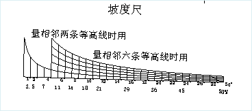
- Adjacent Chart: Auto-generates adjacent sheet diagram. Editable names.
- Adjacent Sheet Numbers: Auto-filled.
- Adjacent Map Names: User-input names.
- Notes:
- Line Spacing: Default 2mm.
- Content: Custom notes input.
- Map Information:
- Line Spacing: Default 2mm.
- Content: Auto-info (date, coordinate system, elevation datum) with editable fields.
- Style Settings
- Text Style: Configure via Text Style Settings dialog.
- Offset: Set element offsets (positive=NE, negative=SW).
- Coordinate System: Set via Projection Settings dialog. Reference Coordinate System Setup.
- Click Generate to create CAD dataset. Results display as:
Notes
- Scales below 1:2,000 require projected coordinate systems (no geographic/planar).
- Scales ≥1:2,000 support only User Custom or National Coordinates (Xi'an 1980).