


Feature Description
Using the Situation Simulation Manager, you can create seven types of animations: path animation, blink, attribute animation, show, rotate, scale, and grow.
The precondition for creating animations using the Situation Simulation Manager is that symbols exist in the map or scene and are selected.
Operation steps
- Open the map/scene, click the "Situation Simulation Manager" button in the "Situation Simulation" group under the "2D/3D Plotting" tab to open the "Situation Simulation Manager" dialog.
- Create a new animation group. Right-click in the blank area of the left control in the dialog, select "New" from the context menu to create an animation group. As shown in the figure below.
After selecting a created animation group, additional commands become available in the context menu:

Figure: Create a new animation group - Rename group: Renames the animation group.
- Delete group: Deletes the animation group, including all animations it contains.
- Merge to previous group: Moves animations in the group to the previous animation group and deletes the current group.
- Clear group: Clears all animations in the group.
- Move up: Moves the animation group up.
- Move down: Moves the animation group down.
- Create an animation. Select symbols in the scene, choose the desired animation type from the left dropdown list, such as path animation, as shown below:
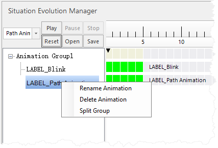
Figure: Create an animation Right-click on the created animation to access available commands in the context menu:
- Rename animation: Renames the animation.
- Delete animation: Deletes the currently selected animation.
- Split group: Splits the animation group based on this animation.
- Modify animation properties. On the "Animation Properties" tab, adjust properties for the selected animation.
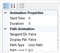
Figure: Modify animation properties Start Time: Modify the animation start time using two methods: directly change the "Start Time" value in the properties panel, or left-click and drag the corresponding timeline bar.
Duration: Modify the animation playback duration using two methods: directly change the "Animation Play Time" value in the properties panel, or right-click and drag the corresponding timeline bar.
Additionally, each animation type has specific properties, described as follows:
- Path Animation
- Tangent direction: Sets whether the animated object moves along the tangent direction. For vector or model fill point symbols, the symbol automatically adjusts its orientation based on the path angle.
- Display path: Sets whether to display the path during animation playback.
- Path type: Sets whether the animation path is a line path or curve path.
Additionally, path animation requires setting path points. Select the "Path Point Manager" tab with the following functions:
 Add button: Click at appropriate observation positions in the scene to add path points via mouse; modify longitude, latitude, and altitude in the parameters below.
 Edit button: Select a path point in path animation, click this button, then click the mouse at a suitable scene position to modify the selected path point location.
 Delete button: Select a path point to delete it individually; select a path node to delete the entire path line.
- Blink
- Blink style: Sets blinking based on "Blink Frequency" or "Number of Blinks".
- Blink interval (milliseconds): If blink style is "Blink Frequency", sets the interval between blinks in milliseconds.
- Blink times: If blink style is "Number of Blinks", sets the total number of blinks for the animation.
- Color alternates: Sets whether blinking includes color alternation.
- Alternate colors: If color alternates, sets the alternate colors for blinking.
- Start color alternates: If color alternates, sets the start alternate colors for blinking.
- Attribute Animation
- Line color animation: Sets whether line color animation is enabled.
- Start line color: If line color animation is enabled, sets the start line color.
- End line color: If line color animation is enabled, sets the end line color.
- Line width animation: Sets whether line width animation is enabled.
- Start line width: If line width animation is enabled, sets the start line width.
- End line width: If line width animation is enabled, sets the end line width.
- Surrounding line width animation: Sets whether surrounding line width animation is enabled.
- Start surrounding line width: If surrounding line width animation is enabled, sets the start surrounding line width.
- End surrounding line width: If surrounding line width animation is enabled, sets the end surrounding line width.
- Surrounding line color animation: Sets whether surrounding line color animation is enabled.
- Start surrounding line color: If surrounding line color animation is enabled, sets the start surrounding line color.
- End surrounding line color: If surrounding line color animation is enabled, sets the end surrounding line color.
- Show
- Display status: Sets the final display state. True indicates the symbol ends as visible, False indicates invisible.
- Display effects: Sets whether a fade effect is applied.
- Rotate
- Direction: Sets rotation as clockwise or counterclockwise.
- Start rotation angle: Sets the start rotation angle for X, Y, and Z axes.
- End rotation angle: Sets the end rotation angle for X, Y, and Z axes.
- Scale
- Start scale: Sets the start scale for scaling.
- End scale: Sets the end scale for scaling.
- Grow
- Start scale: Sets the start scale for growing.
- End scale: Sets the end scale for growing.
Specific animations supported by different symbol types are shown in the table below:
Table: Animation support description for point, line, and region symbols Animation type Point symbol vector mode Point symbol billboard mode Point symbol model fill Line and region symbols Path animation √√√XBlink √√√√Attribute animation √√X√Show √√X√Rotate √X√XScale √√√XGrow XXX√
- Path Animation
- After setting up animations, use the "Play", "Pause", "Stop", and "Reset" buttons for playback control.
- Save and open animations. After creation, click "Save" to save animations as an XML file. The "Open" button loads saved animation XML files into the Situation Simulation Manager for property modifications.
 Notes:
- When creating animations, the target symbol objects must be selected first.
- Animation playback occurs per animation group; one group completes before the next starts.
- The animation start time is relative to the animation group.
Related topics