


In the Marker Symbol Editor, each geometry drawn in the symbol editing area during symbol creation is called a stroke, meaning every geometry constituting a point symbol is defined as a stroke. When creating point symbols, users can draw point features, line features, polygon features, and text within the valid range of the symbol editing area. All elements drawn within this valid range will ultimately form the graphical components of the point symbol. As these elements can be points, lines, polygons, or text, the strokes of point symbols are correspondingly categorized into four types: point, line, polygon, and text.
The Stroke Manager panel located in the lower-left corner of the Marker Symbol Editor organizes and manages each stroke within the point symbol created in the symbol editing area. This panel consists of a toolbar and a stroke list: The toolbar contains function buttons for stroke management, while the stroke list displays all strokes constituting the point symbol (i.e., those drawn in the symbol editing area), with each list item representing an individual stroke.
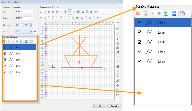
Stroke List
- Each item in the stroke list corresponds to a stroke in the point symbol, representing a geometry drawn in the symbol editing area.
- The name and icon of each stroke item indicate the geometry type it represents.
- The checkbox at the beginning of each stroke item controls its visibility in the symbol editing area. A checked box means the stroke is visible; unchecked means hidden.
- The order of items in the stroke list reflects their stacking sequence in the symbol editing area. Strokes listed earlier are displayed above those listed later.
- Selecting a stroke item in the list will simultaneously select its corresponding geometry in the symbol editing area, and vice versa.
Stroke Manager Toolbar
The functions and usage of buttons on the Stroke Manager toolbar are as follows:
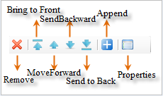
- Remove: Deletes selected strokes from the list. Select strokes using Shift or Ctrl keys for multiple selection, then click this button to delete.
- Bring to Front: Moves the selected stroke to the top of the list, placing it above all other strokes in the editing area.
- Move Up: Shifts the selected stroke one position upward in the list, placing it before its preceding stroke.
- Move Down: Shifts the selected stroke one position downward in the list, placing it after its following stroke.
- Send to Back: Moves the selected stroke to the bottom of the list, placing it below all other strokes in the editing area.
- Append Symbol: Adds vector point symbols from other symbol libraries as composite strokes to the current symbol. Operation steps:
- Click Append Symbol to open the Select Symbol window, which resembles the Marker Symbol Selector and displays point symbols from the current library. Select desired symbols and click OK to add;
- Use the Symbol Library Management button in the Select Symbol window to access the Symbol Library Management dialog. Through the Add Symbol Library option, users can import other marker symbol library files and select vector point symbols from them as append targets;
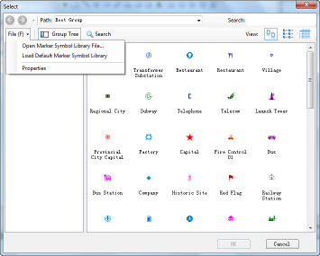
- In the Select Symbol window, select vector point symbols to append as composite strokes. Multiple symbols can be selected, with each symbol corresponding to a separate composite stroke;
Note: Multiple point symbols can be selected as append targets, with each forming an individual composite stroke.
- After selecting symbols, click OK to complete appending. The added composite strokes are placed at the top of the stroke list by default.
- Properties: Configures style settings for selected strokes. Select one or multiple strokes and click Properties to open the Properties dialog. The dialog content varies depending on stroke type. For stroke style configuration details, refer to: Setting Point Symbol Stroke Styles.
 Notes:
- When multiple strokes of different types are selected, the Properties dialog displays attributes of the topmost stroke type in the selection.