


Introduction To The 3D Linear Symbol Editor Interface
Structure of the 3D Linear Symbol Editor Interface
Basic Structure of the 3D Linear Symbol Editor Interface
The following figure shows the layout of the 3D linear symbol editor interface:
- Symbol Properties: The Symbol Properties area is used to set or modify attributes of 3D linear symbols, including: Symbol ID and Symbol Name.
- Subline Management: The Subline Management area manages sublines that constitute 3D linear symbols. It includes functions for adding/deleting sublines, adjusting subline hierarchy, and setting subline types.
- Preview Area: Displays the results of the user-created and edited 3D linear symbols in real time. The preview area provides basic viewing operations to meet various preview requirements.
- Snapping Setting: A snapshot captures the current 3D linear symbol creation result as an image, which is used for symbolization when applying 3D symbols to 2D maps. Users can set snapshots for current 3D linear symbols or clear existing snapshots.
- Subline Property Settings: Configures properties for sublines. By adjusting these properties, users can create 3D linear symbols with different styles. Available properties vary by subline type. For details, refer to the "Structure of Subline Property Settings Area" section.
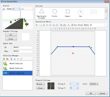 |
| Structure Diagram of 3D Linear Symbol Editor |
Structure of Subline Property Settings Area
- Property Settings Area for Cross-Section Sublines
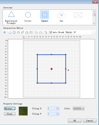
The left figure below shows the structure of the cross-section subline property settings area. Its functional zones include:
- Interactive Editing Area: Provides tools for drawing and editing cross-section geometries, along with rulers and grid background.
- Recently Used Section List: Displays recently used cross-sections and supports symbol import for quick construction.
- Texture Settings: Configures line color, texture images, and texture repeat parameters.
- Property Settings Area for Model Sublines
The right figure below shows the structure of the model subline property settings area. Its functional zones include:
- Recently Used Model List: Displays recently used 3D markers or imported models for quick selection.
- Virtual-Real Mode Settings: Configures virtual-real mode to enrich model subline types. For details, refer to Creating Model Sublines.
- Model Offset and Rotation Settings: Adjusts X/Y/Z offsets and rotation angles of models.
 |
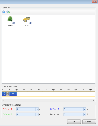 |
| Structure Diagram of Cross-Section Subline Property Settings Area | Structure Diagram of Model Subline Property Settings Area |
Preview Area Navigation Operations
The 3D linear symbol editor displays real-time spatial effects (along X/Y/Z axes) in the preview window. As shown below, users can adjust viewing angles using mouse controls to preview 3D effects. Detailed operations are as follows:
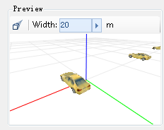 |
| Previewing Linear Symbols |
- Mouse Operations:
- Left-click drag: Pan the 3D preview.
- Mouse wheel scroll: Zoom in/out.
- Middle-click drag: Adjust pitch angle.
- Right-click drag: Zoom in/out.
- "
 ": Reset to default viewpoint.
Combining these operations allows multi-angle previewing for optimal 3D symbol adjustment.