


The process of creating a model subline mainly includes the following steps:
- Create a model subline;
- Select models to compose the model subline;
- Set properties of models in the model subline, including spacing and rotation angle;
- Set offset for the model subline.
Creating a Model Subline
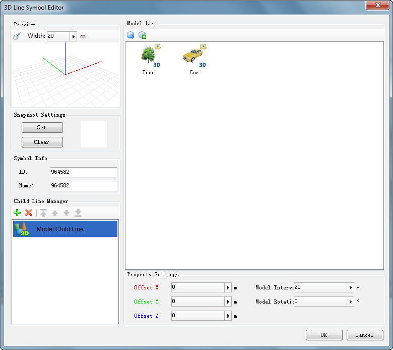
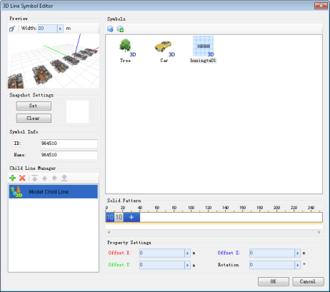
After opening the 3D linear symbol editor, a default subline of cross-section type is automatically created in the subline management list. Double-click the subline to activate a drop-down list (as shown in middle figure). Click the drop-down button and select "Model Subline" from the list to complete creation.
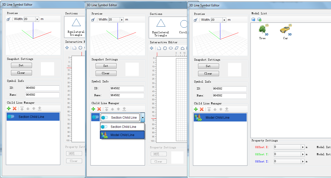 |
| Default state after opening 3D linear symbol editor |
Alternatively, create a new model subline through:
- Click the "
 " button on the subline management toolbar to add a subline;
 - Double-click the new subline to activate a drop-down list, then select "Model Subline".
Selecting Models for Model Subline
Two methods are available to obtain models for model subline: 1) Select a 3D marker from marker symbol library; 2) Import a 3D model file (*.sgm or *.3ds).
Below details both methods:
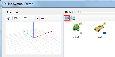
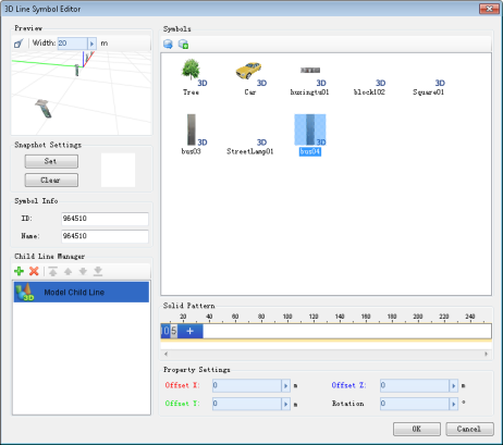
Import 3D Marker
- Click "Import 3D Symbols" button (
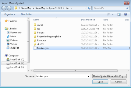
 ), which opens the "Import Marker Symbol" dialog;
- In the dialog, select and open the marker symbol library file containing desired 3D marker;
- The "Select Symbol" dialog displays symbols from the opened library. Choose the target 3D marker;
The "Select Symbol" dialog supports standard symbol library management operations. Users can open other marker symbol libraries via the "File" menu to select required 3D markers.
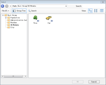
- After importing, the 3D marker appears in the model list. Select it to preview the model subline effect.
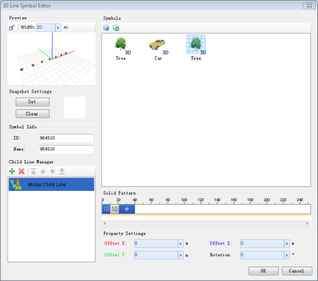
Importing 3D marker Selecting model for subline
Import 3D Model
- Click "Import 3D Model" button (
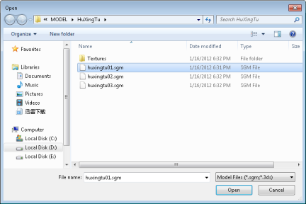
 ), which opens the file dialog;
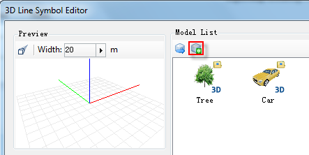
- Select and open the target 3D model file (*.sgm or *.3ds);
- The imported model appears in the list. Select it to preview the model subline effect.
Importing 3D model Selecting model for subline
Use the "Symbol Angle" property in "Subline Property Settings" to adjust model rotation. Input values directly or use slider/buttons.
Setting Model Properties
"Model Spacing" controls distance between adjacent models along the line.
"Model Angle" controls horizontal rotation of models.
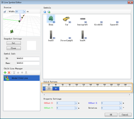 |
Setting Model Subline Offset
Use "X Offset", "Y Offset", and "Z Offset" in "Subline Property Settings" to adjust positional offsets (in meters). Input values directly or use slider/buttons.
The preview area displays 3D coordinate axes: red (X), green (Y), blue (Z). Offset properties use corresponding colors for intuitive distinction.
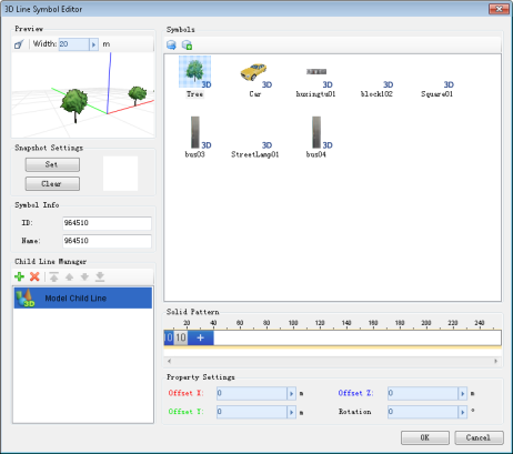 |
 Note
Note
- This feature is currently unavailable in Java desktop version, scheduled for release after v11.1.