When there is an object in the selected KML layer in the scene, click the right mouse button and select the Attribute command in the pop-up Context Menu to pop up the KML Properties "panel. The detailed Attributes for Select Objects are displayed in the KML Properties "panel.
The Object Info and Object Style of Select Objects can be viewed or set in the KML Properties "panel. The following details the specific content of each type of information.
When you click the Object Info "tab in the KML Properties" panel, the panel displays information such as the spatial properties of Select Objects, which you can modify. If the Enable Instant Refresh "check box is checked, the changes made to the KML Object Properties will be applied to the selected object in real time.
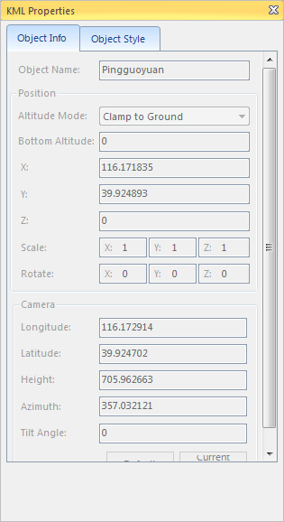 |
| Figure: Object Info "Tab |
- Object Name: Displays the name of the Select Objects.
- Location:
- Height mode: Set the height mode used by the selected KML object. For height mode, see the detailed introduction of About the height mode .
- Extended Height: If the height mode of Select Objects is Relative to Ground or Absolute, in the combo box to the right of "Extended Height", Sets the elevation value of the object's location from the Earth's surface.
- Location (X, Y, Z): the geographic location of Select Objects, namely, latitude and longitude coordinates X, Y (in degrees) and elevation information Z (in meters). If the selected object is a Model Object, the position indicates the position of the bottom center point of the Model Object; if the Select Object is a landmark, the position of the landmark point.
- Zoom:
- Scale (X, Y, Z): Select Objects' Scale Factor values in X, Y, Z directions. Valid only for Model Objects.
- Rotate:
- Rotation (X, Y, Z): Rotation angle values of Select Objects, including rotation angle values around X, Y, Z axes. Valid only for Model Objects. Also, Surface Mapping supports setting the rotation Z value.
Camera:
- Camera: This area is used to set the camera position, azimuth angle and tilt angle for observing the Select Objects, that is, the final observation angle of the flight when the object is flown in 3D.
In Layer Manager, double-click an object node under the KML layer to fly the object in the KML layer, and the flying destination is the camera position set in the Spatial Info of the object.
TheCurrent Camera "button is used to set the Camera Settings of the current scene to the Camera Parameters of Select Objects. The "Default" button is used to reset the Camera Parameters of the current scene to the default values, that is, to use the latitude and longitude of the object position and an altitude of 1000 m as the default Camera Parameters.
- Camera: This area is used to set the camera position, azimuth angle and tilt angle for observing the Select Objects, that is, the final observation angle of the flight when the object is flown in 3D.
- Description: Remarks used to set Select Objects.
Click the Object Style "tab in the KML Properties" panel. Select Objects style information is displayed in the right area of the dialog box, and you can modify the Select Objects style here.
Different types of objects in theselected KML layer have different setting contents of Object Style, which can be divided into landmark, surface object, line object, model and Surface Mapping.
- When the
- selected object is Landmark, the setting content of Object Style is shown in the following figure:
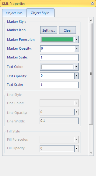
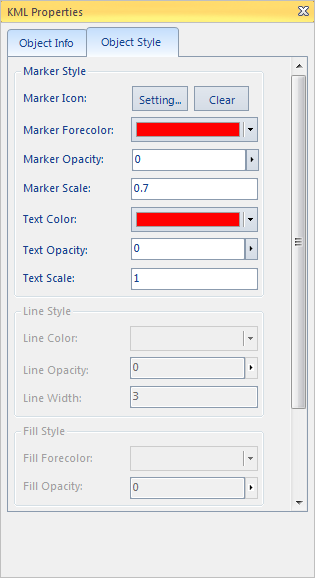
- Marker Icon: Set the picture object to replace the point symbol displayed by the landmark object. Click the "Settings" button to pop up the "Open Icon Files" "dialog box, and select the opened Icon Files (*.PNG). The "Clear" button is used to cancel the picture object used by the point.
- Foreground color of landmark: Set the display color of the point symbol part of the landmark object. Click the Color button to select and set the color to be used in the pop-up color panel. Note: Since the landmark has its own color, after setting the foreground color of the landmark, the display color of the landmark is the superimposed color of the setting color and the landmark's own color, which is slightly different from the color in the setting combo box.
- Landmark Transparency: Set the transparency effect of the point symbol part of the landmark object. The value is an integer value from 0 to 100, with 0 being completely opaque and 100 being completely transparent.
- Scale Factor: Sets the scale factor of the point symbol part of the landmark object.
- Text Color: Sets the Text Color of the text mark part of the landmark object. Click the Color button to select and set the color to be used in the pop-up color panel.
- Text Transparency: Set the transparency effect of the text in the text identification part of the landmark object. The value is an integer value from 0 to 100, with 0 being completely opaque and 100 being completely transparent.
- Scale Factor: Sets the scale factor of the text of the text identification part of the landmark object.
- When the selected object is Model Object, the setting content of Model Object is as shown in the following figure:
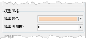
- Model Color: Set the Fill Color of Model in the pop-up color panel.
- Model Transparency: Set the transparency effect of Fill Color of Model Object. The value is an integer value from 0 to 100, with 0 being completely opaque and 100 being completely transparent.
- When the selected object is Line Object, the setting content of Object Style is as shown in the following figure:
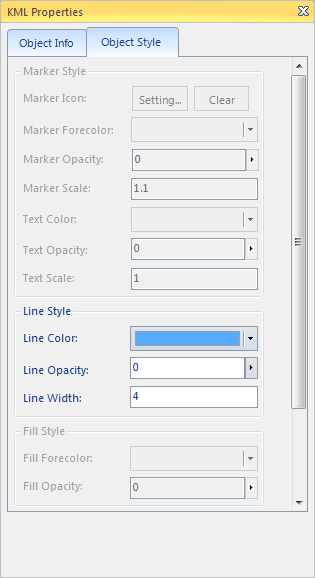
- Linetype Color: Sets the display color of line objects. Select and set the color of the line in the color panel that pops up by clicking the color button.
- Line Transparency: Set the transparency effect of the line object. The value is an integer value from 0 to 100, with 0 being completely opaque and 100 being completely transparent.
- Lineweight: Sets the lineweight of a line object.
- When the selected object is Face Object, the setting content of Object Style is shown in the following figure:
- Line style:
- Linetype Color: Sets the display color of the contour line of the face object. Select and set the color of the line in the color panel that pops up by clicking the color button.
- Line Transparency: Set the transparency effect of the contour line of the face object. The value is an integer value from 0 to 100, with 0 being completely opaque and 100 being completely transparent.
- Line Width: Sets the line width of the contour line of the face object.
- Fill Style:
- Fill foreground color: Set the Fill Color of the face object. Select and set the color of the line in the color panel that pops up by clicking the color button.
- Fill Transparency: Sets the transparency effect of the face object. The value is an integer value from 0 to 100, with 0 being completely opaque and 100 being completely transparent.
- Line style:
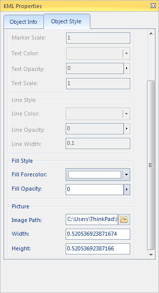
- When the selected object is Surface Mapping, the setting content of Object Style is as shown in the following figure:
- Fill Style:
- Fill foreground color: Set the Fill Color of the face object. Select and set the color of the line in the color panel that pops up by clicking the color button.
- Fill Transparency: Sets the transparency effect of the face object. The value is an integer value from 0 to 100, with 0 being completely opaque and 100 being completely transparent.
Image:
- Picture Path: Click the button on the right to Select Picture as Surface Mapping in the pop-up "Open" dialog box, or directly enter the path and name of the picture in the text box.
- Image Width: used to display and set the display width of the selected Surface Mapping image.
- Image Height: Used to display and set the Show Altitude of the selected Surface Mapping image.


