Line conversion Flying Route
Instructions for use
The " Flying Route" group in the " Flying Management" tab adds functions related to 3D flying, such as the creation, conversion, deletion, and Stop Management of 3D Flying Routes.
- The Convert From Line function is used to convert line data directly to a Flying Route or to convert nodes on a line object to sites.
- The line data that can be converted into the flight path is divided into two-dimensional line data and three-dimensional line data. 2D line data is a 2D line that contains only X and y coordinates; 3D line data is 3D line data that contains Z coordinates (height coordinates) on the basis of 2D lines.
- The Convert From Line Drop-down Button in the Flying Route group is available when there is a 2D or 3D line data object selected in the scene.
Operation steps
- Click the Convert From Line Drop-down Button. A drop-down menu pops up that provides the ability to convert a selected line object to a flight path or to add a node of a line object as a flight site.
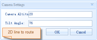
- When flight path conversion is performed from two-dimensional data:
- Convert From Line to Path: Click this item to pop up the "Camera Settings" dialog box. After the user sets the parameters such as camera height and tilt angle, the node of the selected line object can be converted into a new flight path. Each node will act as a site on the Flying Route. For the converted path Parameter Settings, see Parameter Settings in the Create a Flying Route .
- Convert From Line to Site: Click this item to pop up the "Camera Settings" dialog box. After setting the parameters such as camera height and tilt angle, the node of the selected line object can be added as the site in the current flight path. For Parameter Settings of the converted site, see Parameter Settings in the Create a Flying Route .
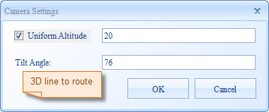
- When flight path conversion is performed by 3D Data:
- Convert From Line is path: Click this item to pop up the Camera Settings "dialog box as shown in the following figure. After the user sets such Parameters as the height and inclination angle of the unified aircraft, the node of the selected line object can be converted into a new flight path. Each node will act as a site on the Flying Route. See Parameter Settings on the Create a Flying Route .
- The Convert From Line is site: Click this item to pop up the Camera Settings "dialog box as shown in the following figure, and set the Uniform Camera Altitude and inclination angle and other Parameters. The node of the selected line object is added as a station in the current flight path. See Parameter Settings on the Create a Flying Route .
 |
| 2D Line Conversion Camera Settings Dialog Box |
 |
| 3D Lines Convert Camera Settings Dialog Box |
Note: The Z coordinate value of the node in the 3D line data is directly converted into the camera height of the corresponding station in the flight path. If the " Uniform Camera Altitude" check box is selected, it will be the United Value Settings of the flight path again.


