Mosaic
Usage Instructions
When TIN terrain exists in the spherical scene window, use a polygon (2D/3D region) to mosaic the specified terrain.
Applicable scenarios: When existing terrain data does not strictly match the model — for example, roads or retaining walls are covered by the terrain, or tunnel entrances are occluded by the terrain — the Mosaic function can be used to mosaic the model’s boundary surfaces with the TIN terrain, ensuring a proper fit between the terrain and the model.
Function Entry
- 3D Geographic Design tab → TIN Terrain Operations group → Mosaic button
- Toolbox → 3D Data → TIN Processing → TIN Mosaic
Operation Steps
- Prepare mosaic regions: Use the Extract Boundary function (under the 3D Geographic Design tab → Model Operations group → Section & Projection drop‑down button → Extract Boundary) to extract the boundary surfaces of models that are covered or occluded by the terrain. For detailed instructions, see Extract Boundary. After extraction, add the resulting region dataset to the scene as mosaic regions.
- In the TIN Terrain Operations group under the 3D Geographic Design tab, click Mosaic to open the “TIN Mosaic” panel.
- Layer selection: Click the drop‑down arrow in the “TIN Terrain” combo box and select the layer containing the object to be mosaicked.
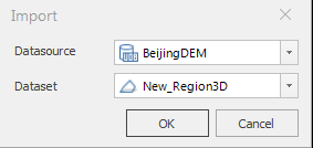
- Define mosaic regions: Select either “Select Region” or “Draw Region” to determine the mosaic region type. When “Draw Region” is selected, the toolbar provides three methods for drawing mosaic regions: “Rectangle”, “Polygon”, and “Import”. Clicking the Import button opens a dialog box as shown below.
 Note:
Note:Mosaic regions must meet the following requirements:
- Topologically valid: No self‑intersections, dangling edges, or other topological errors.
- Non‑zero area: The projected area must not be zero.
- Spatially non‑conflicting: Mosaic regions must not overlap in projection (e.g., direct region‑on‑region overlap, or “vertical overlap” with empty space in between) and must not intersect or cross each other in 3D space.
Additionally, to ensure processing efficiency, it is recommended to control the geometric complexity of mosaic regions to avoid excessive computation time.
- “Preview” check box: The “Preview” check box is checked by default, allowing real‑time preview of the mosaic effect. However, the slope transition effect is not previewed.
- Parameter settings: Used to set parameters such as additional height, berm width, and the effective height range.
- Additional Height: Sets an additional height for the mosaic region. This operation does not change the original value of the mosaic region. The default is 0 (in meters). Enter a value directly to specify the additional height.
- Berm Width: Sets the width of the slope transition at the boundary between the mosaic region and the terrain. The default is 0 (in meters); you can enter a value directly. The berm width helps create a smoother transition between the mosaic region and the terrain.
- Effective Height Range: When checked, allows setting the height range for the mosaic operation.
- Bottom Elevation: Sets the bottom elevation value relative to the mosaic region, in meters. This value determines how far downward from the mosaic region data will be included in the mosaic calculation.
- Top Elevation: Sets the top elevation value relative to the mosaic region, in meters. This value determines how far upward from the mosaic region data will be included in the mosaic calculation.
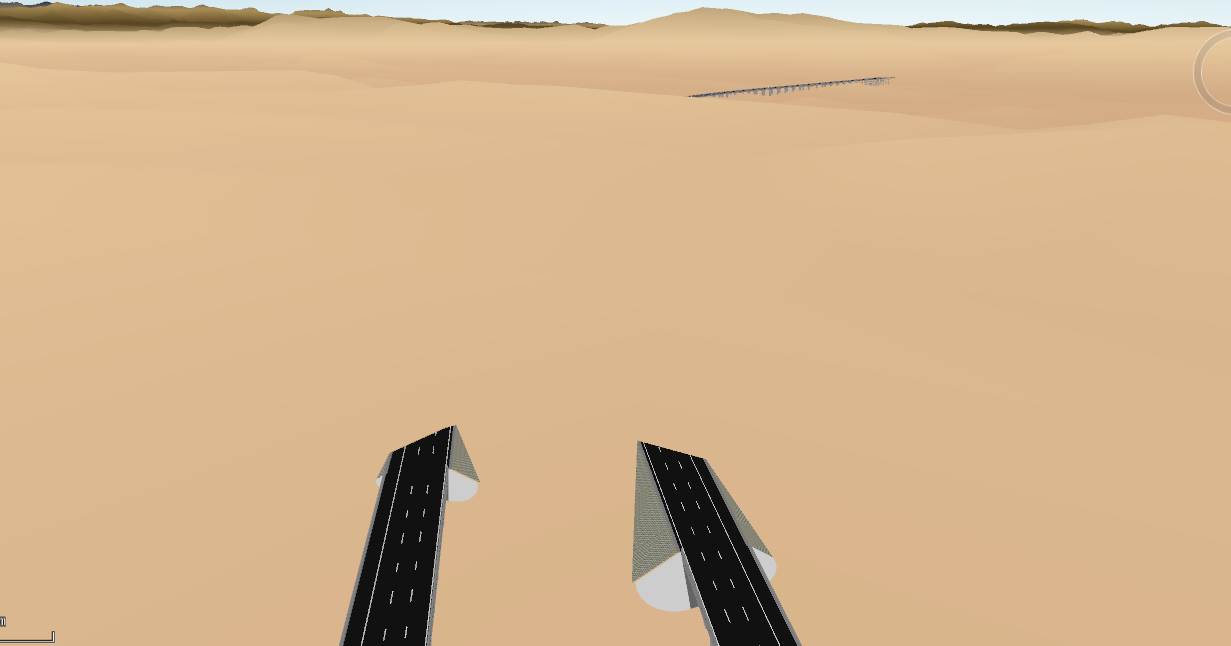
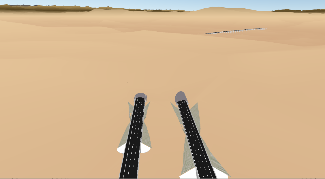
- Click “OK” to perform the TIN terrain mosaic. You can also click the “Undo” button to revert the TIN terrain mosaic operation. Example mosaic results are shown below: the left image shows the terrain before the mosaic operation, and the right image shows it after.