


Common 3D effect maps include the following two types:
3D orthophoto
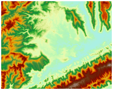
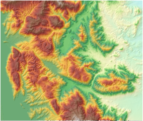
The 3D orthophoto generated from DEM can achieve three-dimensional terrain visualization effects. As shown in Figure 1 and Figure 2, 3D orthophoto exhibits distinct stereoscopic effects, effectively conveying regional terrain characteristics and facilitating understanding of mountainous topography. When overlaid with other thematic information, it assists in various spatial analyses such as site selection.
The "3D orthophoto" function uses elevation variations from surrounding raster cells to calculate brightness values through 3D projection of DEM. It then renders DEM brightness values using specified color tables and NoData colors to generate 3D orthophoto.
 |
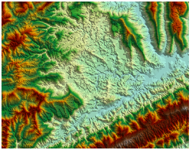 |
| Figure 1: Original raster image | Figure 2: 3D orthophoto |
3D hillshade
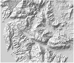
The "3D hillshade" function generates shaded relief maps by simulating light source angles and shadows on raster surfaces. This technique produces realistic terrain representation through calculated slope aspect information from raster data. Slopes facing the light source receive higher grayscale values, while shadowed areas receive lower values. The computed hillshade raster provides vivid 3D visualization of landforms.
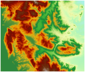
3D hillshade is primarily used for visualization. By overlaying original raster (Figure 3) with hillshade (Figure 4) and adjusting raster layer transparency, users can create detailed 3D terrain maps (Figure 5). Optimal cartographic results require parameter adjustments like transparency and brightness. Additional layers (e.g., land use, roads, rivers) can be added to enrich map information.
 |
 |
 |
| Figure 3: Original raster | Figure 4: 3D hillshade | Figure 5: Overlay effect |
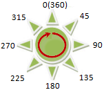
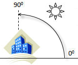
Generating 3D hillshade requires specifying an imaginary light source position defined by azimuth and altitude angles:
 |
 |
- Azimuth determines light direction using angular measurements from 0° (due north) clockwise through 360°. Default value: 315° (northwest).
- Altitude specifies light source elevation from 0° (horizontal) to 90° (vertical). Default value: 45°.
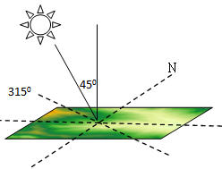
Figure below shows the spatial relationship when using default parameters (azimuth 315°, altitude 45°):
 |
Related Topics