


 Feature Description
The Generate Surface Distance Raster function produces three output datasets: Surface Distance Raster, Surface Direction Raster, and Surface Allocation Raster based on source datasets and surface raster inputs.
Surface Distance Raster: Represents the shortest surface distance from each cell to the nearest source across the surface raster. The nearest source is determined by the minimum surface distance among all possible sources. No-data cells in the surface raster remain as no-data in the output. The surface distance calculation between adjacent cells (g1 to g2) uses the following resampling method:

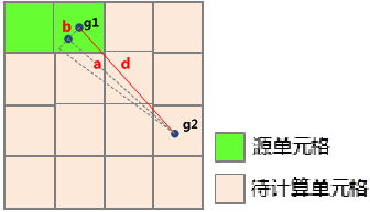
Where b represents the elevation difference between cells g1 and g2; a denotes the Euclidean distance between their centroids. For orthogonally adjacent cells (up/down/left/right), a equals cell size. For diagonally adjacent cells, a equals cell size multiplied by √2.
Surface Direction Raster: Indicates the travel direction from each cell to its nearest source along the shortest surface path. Eight possible directions (N, S, W, E, NW, SW, SE, NE) are encoded using integers 1-8. Source cells are assigned 0, while no-data cells receive value 15.

Surface Allocation Raster: Identifies the nearest source for each cell using the source's original value (raster value for raster sources, SMID for vector sources). No-data cells in the input surface raster remain no-data in the output.
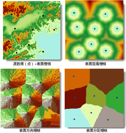
Example: Using hospital locations (point dataset) and regional DEM data, the analysis produces:
- Surface Distance Raster: Travel distance from each cell to the nearest hospital.
- Surface Direction Raster: Direction to the nearest hospital.
- Surface Allocation Raster: Service areas divided among eight hospitals.
Feature Entry
- Spatial Analysis Tab -> Raster Analysis Group -> Distance Raster Drop-down Button -> "Generate Distance Raster (Surface)"
- Toolbox -> Raster Analysis -> Distance Raster -> Generate Distance Raster (Surface)
Steps
- Source Data Settings: Select source dataset (vector or raster data) representing features of interest (e.g., wells, schools).
- Surface Raster Configuration: Specify DEM dataset for surface analysis.
Note: Surface raster values can represent elevation, slope, or other cost factors affecting movement.
- Parameters: Configure analysis parameters:
- Maximum Uphill Angle: Maximum allowable angle between uphill direction and horizontal plane (default: 90°, unrestricted).
- Maximum Downhill Angle: Maximum allowable downhill angle (default: 90°, unrestricted).
- Max Distance: Threshold distance (default 0=unlimited). Cells exceeding this distance receive no-data values.
- Resolution: Output cell size (default: 1/500 of input dataset's diagonal length).
Note: Restrictive angles may result in no valid paths.
- Result Configuration: Specify output names for distance, direction, and allocation rasters (default: result_SurfaceDistance, result_SurfaceDirection, result_SurfaceAllocation).
- Click "Environment Settings" to configure geographic extent, clip bounds, and cell size. See Analysis Environment Settings.
Note: Environment parameters can be set as global defaults for subsequent analyses.
- Click "Execute" to generate surface distance rasters.
Application Example
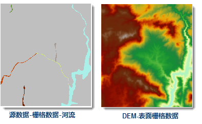
Analyzing river accessibility using DEM data:
- Surface Distance Raster: Minimum travel distance to rivers.
- Surface Direction Raster: Optimal directions to nearest rivers.
- Surface Allocation Raster: Watershed areas assigned to river segments.

 Related Topics
 Generate Straight-Line Distance Raster
Generate Custom Cost Distance Raster