


For different elements in the 3D pipeline scene, different methods can be used to quickly construct the 3D pipeline scene. Usually, 3D line symbols are used to construct 3D pipelines, and self-adaptive pipe point symbols are used to construct 3D pipe points. Some special feature points, wells and ancillary facilities are displayed by 3D Marker. After adding 3D Piple Line on the desktop, create or import adaptive pipe point symbols, and set 3D point and line symbols, you can build a real and beautiful underground 3D pipeline scene with Display Effects. The specific operation is as follows:
Add 3D Piple Line
- Select the built 3D Network Dataset, and select Add to New Spherical Scene "in the Context Menu.
- In Layer Manager, individually select the pipeline and pipepoint layers for the 3D Network Dataset, and in the Style Settings "tab, set the layer Height Mode to Absolute, and if the data is from underground, set Data From to Underground.
- In the Underground group in the Scene tab, set Underground Mode to On and set Transparency to 50%.
Building the Underground Pipelines Scenario
3D Pipeline Construction
According to the complexity of pipelines in the actual scene, there are two ways to construct 3D pipelines by configuring pipeline symbols:
- Use a pipeline symbol by setting the Layer Style of the pipeline layer;
- Use two or more pipeline symbols by creating a 3D Custom Map.
Use a pipeline symbol
- Select a pipeline layer in Layer Manager, right click and select Layer Style "to open the Line Symbol Selector" dialog box;
- Select 3D Linetype in the Line Symbol Selector ", click the symbol to be set, and change the Line Width and Line Color of the symbol as the case may be;
- After you set the linetype symbol for 3D routes, the default adaptive tube point symbol is displayed. The default adaptive pipe Point Symbol Color is consistent with the color of the pipeline, with a hoop. The length of the hoop is 0.015m, and the bend of the elbow pipe point is a sharp angle, as shown in the following figure.
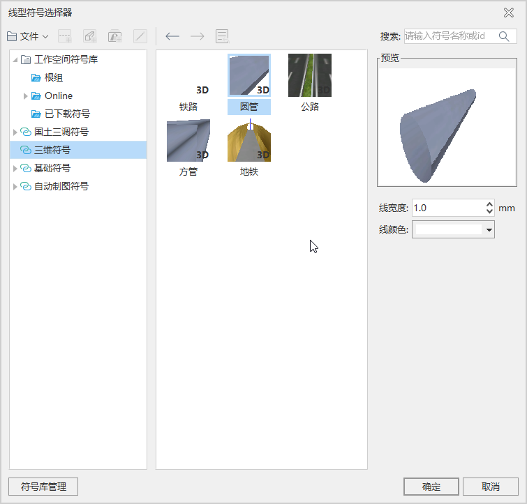 |
| Figure: Line Symbol Selector. |
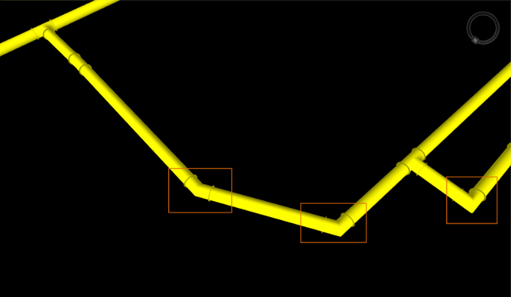 |
| Figure: Default Adaptive Tube Point Symbol |
Note:
- The minimum value for the width of lines on a layer is 0.1 meters. Setting a smaller value will treat it as 0.1 meters.
- If you need to specify a pipeline width smaller than 0.1 meter, you can set the horizontal and vertical Scale Factors for each pipeline separately in the Field of the Horizontal and Vertical Scale Factors of the Line Type symbol.
- It is recommended to specify the pipeline width as 1, and then control the actual line width of the pipeline through the horizontal and vertical Scale Factors of the pipeline.
Using Multiple Pipeline Symbols
If the linetype symbols, colors, and line weights used by the pipelines of a layer are different, you can implement multiple types of linetype symbols by making a 3D Custom Map .
- In Layer Manager, select the pipeline layer, right-click, select Create Thematic Map ", and in the Create Thematic Map" dialog box that opens, select Custom Thematic Map ";
- Line Type parameter
- Line Style: Set the Line Style by selecting the Property Field where the Line Style is stored from the drop-down menu;
- Line Color: Select the Line Color from the Property Field that stores the line type color through the drop-down menu;
- Line Width: Select the Line Type width from the Property Field that stores the line type width in the drop-down menu;
- Material Name: Set the material path by selecting the Property Field that stores the material name from the drop-down menu.
- Click Apply to complete the thematic map.
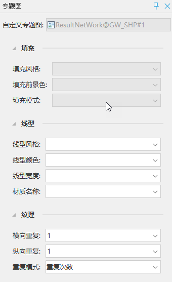 |
| Figure: Setting the Custom Thematic Map Linetype Field |
Construction of 3D tube point
Three-dimensional pipe points are divided into three categories of elements: feature points, wells and ancillary facilities. Three-dimensional adaptive pipe point symbols can be used to construct straight, tee, cross, elbow and other feature points, while some special feature points, wells and ancillary facilities continue to use 3D Marker to display such pipe points with complex structure and special appearance.
According to the complexity of tube point symbols in the actual scene, there are two ways to construct 3D tube points by configuring tube point symbols:
Use a tube point symbol
When all tube points of a layer use one tube point symbol, you only need to set the Layer Style of the tube point layer to the tube point symbol.
- Select the tube point layer, right click and select Layer Style "to open the Marker Symbol Selector" dialog box;
- Select the new adaptive tube point symbol by selecting Model in the Marker Symbol Selector ";
- The comparison effect before and after using the adaptive tube point symbol is shown in the figure below:
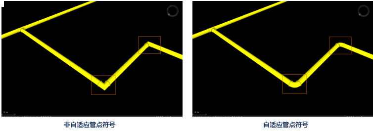 |
| Figure: Before and After Using Adaptive Tube Point Symbols |
Use multiple tube point symbol
For pipe points with complex structure and special appearance such as wells, valves and transformer boxes, Model Symbol is usually used. So how to make some of the tube point layers display as adaptive tube points and some as Model Symbols? That is, by using 3D Custom Map (Theme3D Custom Class), 3D Custom Map allows users to specify several fields for the thematic layer, use the field value of each object in the layer to represent the display characteristics of the object, and set its Model Symbol, rotation, scaling, color and other attributes.
By making a Custom Thematic Map, different types of tube points are displayed according to the Code ID value. The Code ID value can be taken in the following ways:
- When the pipe point is a characteristic point such as straight, tee, cross, elbow, etc., it is displayed as an adaptive symbol, and the Code ID is set to the number of the created adaptive pipe point symbol or 0;
- When the pipe point is a special pipe point such as a valve, a fire hydrant, or a well, it is displayed as a Model Symbol, and the Code ID is set as the existing Model Symbol number in the symbol library;
- When the pipe point is a normal pipe segment, the Code ID is set to -1.
- Select a tube point layer in Layer Manager, right-click and select Create Thematic Map "Options to open the Create Thematic Map" dialog box, and then select Custom Thematic Map ";
- Set thematic map properties
- Marker Style: select the Property Field storing the Marker Style through the drop-down menu;
- Marker Rotate: Select the Property Field storing the symbol rotation parameter through the drop-down menu;
- Marker Scale: Select the Property Field that stores the scaling parameters of the symbol via drop-down menu.
- Click Apply to complete the thematic map.
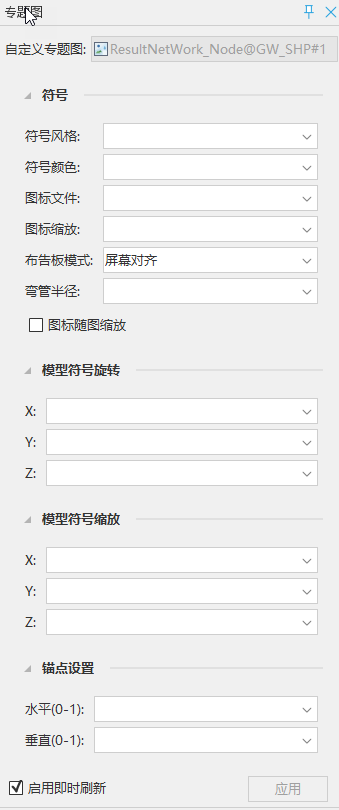 |
| Figure: Custom Thematic MapProperty Settings. |
Precautions
For the data of Underground Pipelines, after the Custom Thematic Map is created, select the newly created thematic map, and set the Height Mode to Absolute and Data from Underground on the Style Settings "tab.
Because the network Topology is not stored in the thematic map, it is necessary to set the parent layer of the pipe point layer as the corresponding pipeline layer when using the Custom Thematic Map to construct the adaptive pipe point. See Layer Styles for details.