Modifying Styles of Custom Thematic Maps
 Introduction
Users can modify all the parameters of the 3D custom thematic map in the Custom Thematic Map window.
Basic Steps
- Selects a 3D custom thematic map layer in the layer manager, and then click New in the Custom group. The pop-up Custom Thematic Map window shows the setting information of the selected custom thematic map.
- Thematic Layer: Sets and shows the currently active thematic map in the Custom Thematic Map window.
- Click the drop-down button of the right combo box. The pop-up drop-down list shows all the current thematic map layers.
- Selects a custom thematic layer as the current layer. The content display of the Custom Thematic Map window is changing according to the selected thematic layer.
- Properties: Sets the fill style, line style, marker style and altitude mode for the selected 3D custom thematic map. The fill style is only available for the region object in the region vector layer; the line style is available for the line object in the line vector layer and the borders of the region object in the region vector layer; the marker style is available for the point object in the point vector thematic layer; the altitude mode is available for the point, line and region vector layer.
- Fill only: Sets the rendering style of the region object in the region layer.
- Fill Symbol: Selects a numerical field or an expression. The system will fill this object according to the value of the field or expression and the style corresponding to the ID of resource fill library. For example, after you finish the setting of a fill symbol field, the value of an object is 8, then the system will search the fill symbol that the ID is 8, and then use the style to render this object. Notes: Currently, the custom thematic map only supports to set the 3D symbols.
- Foreground: Selects a fill foreground field expression. The system will fill the foreground according to the value of the field or expression. Convert the field into 32 bits binary number. From right to left, 0-7 represents R, 8-15 represent G, 16-23 represent B, 24-31 represent A, then select the corresponding colors. For example, if the field value is 1000, convert the 1000 into 32 bits binary number, and it is 0000 0000 0000 0000 0000 0011 1110 1000; then divide this number into 4 parts: 000 0000 (A), 0000 0000 (B), 0000 0011 (G), 1110 1000 (R). The decimal value is A = 0 ,B = 0,G = 3,R = 232. The system will firstly convert the value of the field into a hexadecimal numerical value, and then select its corresponding color. For example, if the value of the field is 1000, the system will firstly convert it into 3E8, secondly add '0' before it into a six-digit number 0003E8, thirdly divide the number into 3 columns 00, 03, E8 (the corresponding decimal value is 16*14+8=232) whose corresponding BGR value is 00 (B), 03 (G), 232 (R), finally select the corresponding color according to the RGB value.
- Fill Mode: Selects a numerical field or an expression. The system will select a fill mode according to the value of the field or expression. 1 means region fill; 2 means the outline fill and 3 means the region and outline fill. When the value isn't 1, 2, or 3, it adopts the default value 1, namely, the region fill.
- Line Style: Sets the rendering style of the line symbols and stretching contour line, or the borders of the region object in the region vector layer.
- Line Symbol: Selects a numerical field or an expression. The system will render this object according to the value of the field or expression and the style corresponding to the ID of resource line library. For example, after you finish the setting of a line symbol field, the value of an object is 8, then the system will search the line symbol that the ID is 8, and then use the style to render this line object.
- Line Color: Selects a numerical field or an expression. The system will set color for a line or a stretching contour line according to the value of the field or expression. The system will firstly convert the value of the field into a 32 bits binary number. From right to left, 0-7 bits represent R value, 8-15 bits represent G, 16-23 bits represent B value and 24-31 bits represent A, then select the corresponding color. For example, if the value of the field is 1000, the system will firstly convert it into 32 bits binary number: 0000 0000 0000 0000 0000 0011 1110 1000. Secondly, divide it into 8 row: 000 0000 (A), 0000 0000 (B), 0000 0011 (G), 1110 1000 (R). The result is in a decimal: A = 0, B = 0, G = 3 and R = 232, finally select the corresponding color according to the RGB value.
- Line Width: Selects a numerical field or an expression. The system will set the line width according to the value of the field or expression. The unit is 0.1mm.
- Marker: Sets the rendering style of the point object in the point layer.
- Marker Symbol: Selects a numerical field or an expression. The system will render this object according to the value of the field or expression and the style corresponding to the ID of resource marker library. For example, after you finish the setting of a marker symbol field, the value of an object is 8, then the system will search the marker symbol that the ID is 8, and then use the style to render this point object.
- Marker Color: Selects a numerical field or an expression. The system will set a marker color according to the value of the field or expression. Convert the field into 32 bits binary number. From right to left, 0-7 bits represent R value, 8-15 bits represent G, 16-23 bits represent B value and 24-31 bits represent A, then select the corresponding color. For example, if the value of the field is 1000, the system will firstly convert it into 32 bits binary number: 0000 0000 0000 0000 0000 0011 1110 1000. Secondly, divide it into 8 row: 000 0000 (A), 0000 0000 (B), 0000 0011 (G), 1110 1000 (R). The result is in a decimal: A = 0, B = 0, G = 3 and R = 232, finally select the corresponding color according to the RGB value.
- Icon File: Selects a text field or an expression. The system will set the full path of the icon file according to the value of the field or expression. Notes: When using the expression to specify the image path, it needs to add English double quotation.
- Marker Scale: Selects a text field or an expression. The system will set the marker scale of the icon file according to the value of the field or expression.
- Billboard Mode: Selects a numerical field or an expression. The system will set the billboard mode according to the value of the field or expression. 1 means the screen aligns at the billboard; 2 means the Z axis aligns at the billboard; 3 means the fixed angle of rotation aligns at the billboard. When the expression isn't 1, 2 or 3, it adopts the default value 1, namely, the screen aligns at the billboard.
- Marker Rotate: Selects a numerical field or an expression. The system will set the angle of rotation that the 3D marker symbol rotates around the X, Y or Z axis according to the value of the field or expression.
- Marker Scale: Selects a numerical field or an expression. The system will set the zoom scale of the X, Y or Z direction of the 3D marker symbol according to the value of the field or expression.
When you create a 3D custom thematic map based on region layer, line layer and point layer, the content of the Custom Thematic Map window are showed in the figure below. The settings differ slightly.
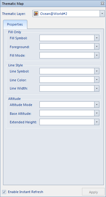 | 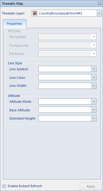 | 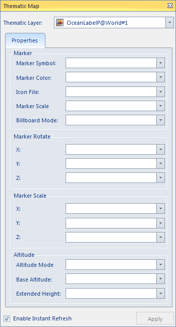 |
| Creating a 3D custom thematic map based on a region layer | Creating a 3D custom thematic map based on a line layer | Creating a 3D custom thematic map based on a point layer |
Note
- WHen setting transparency for region symbols, please note that the attributes of region symbols depend on the region transparency set in the Fill Foreground field.
- The created or modified custom thematic map can be saved as a template which can be used to create new thematic maps in the other layer.
Please see Save as Thematic Map Templates for saving the thematic map template.
- The value of the field and expression corresponds to the ID value in the symbol library. Take for example the marker symbol library, click the Resources node in the Workspace Manager window and then click Fill Symbol Library. The figure below shows the method to view the ID value:
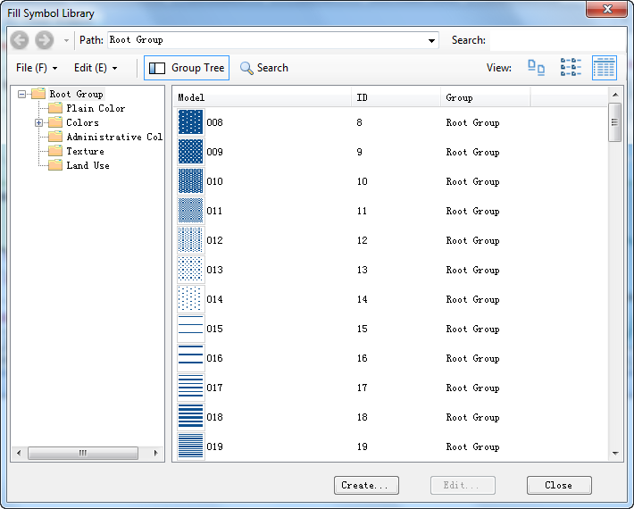 |
| The view window of the marker symbol library |
 Related Topics
 Creating a New 3D Custom Thematic Map
Creating a New 3D Custom Thematic Map Based on Templates