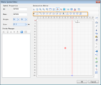
| Point |
Draw a point:
- Click the Point button;
- In the symbol editing area, click the mouse at the target position to complete drawing a point object. To draw another point object, repeat the above steps.
|
| Line |
Draw a polyline:
- Click the Line button;
- In the symbol editing area, continuously click the mouse at target positions to draw control points of the polyline, thereby obtaining a polyline object connected by these control points. Right-click to complete the polyline drawing.
Additionally, polyline control points can be determined either by directly clicking the mouse at appropriate positions or by using the parametric drawing function for precise drawing. The parameters for drawing a polyline are polar coordinates, i.e., by entering the length and angle of the current line segment to draw it. Use the Tab key to switch between the two parameters.
To draw another polyline object, repeat the above steps.
|
| Arc |
Draw a three-point arc:
- Click the Arc button;
- In the symbol editing area, continuously click the mouse at target positions to determine three control points on the arc, thus completing the drawing of an arc. To draw another arc, repeat the above steps.
|
| Circle |
Draw a circular region:
- Click the Circle button;
- In the symbol editing area, click the mouse at the target position to determine the center of the circle;
- Move the mouse and click at an appropriate position to complete the drawing of the circular region. The distance between the clicked position and the center is the radius of the circle. Alternatively, you can enter a value in the displayed numeric box to determine the radius. To draw another circular region, repeat the above steps.
|
| Ellipse |
Draw an elliptical region:
- Click the Ellipse button;
- In the symbol editing area, continuously click the mouse at target positions to determine two control points, completing the drawing of an elliptical region object. The two control points are the endpoints of the diagonal of the minimum bounds of the ellipse. To draw another elliptical region, repeat the above steps.
|
| Parallelogram |
Draw a parallelogram region:
- Click the Parallelogram button;
- In the symbol editing area, continuously click the mouse at target positions to determine two control points, defining one side of the parallelogram;
- Move the mouse and click at an appropriate position to determine the second side of the parallelogram, i.e., the adjacent side to the first, thus completing the drawing of a parallelogram. To draw another parallelogram, repeat the above steps.
|
| Region |
Draw a polygon geometry:
- Click the Polygon button;
- In the symbol editing area, continuously click the mouse at target positions to draw control points of the polygon, thereby obtaining a polygon connected by these control points. Right-click to complete the polygon drawing.
Additionally, polygon control points can be determined either by directly clicking the mouse at appropriate positions or by using the parametric drawing function for precise drawing. The parameters are polar coordinates, i.e., by entering the length and angle of the current polygon side to draw one side of the polygon. Use the Tab key to switch between the two parameters.
To draw another polygon object, repeat the above steps.
|
| Rectangle |
Draw a rectangle:
- Click the Rectangle button;
- In the symbol editing area, continuously click the mouse at target positions to determine the two endpoints of the rectangle's diagonal, completing the drawing of a rectangle. To draw another rectangle, repeat the above steps.
|
| Rounded Rectangle |
Draw a rounded rectangle:
- Click the Rounded Rectangle button;
- In the symbol editing area, continuously click the mouse at target positions to determine the two endpoints of the diagonal of the rounded rectangle's minimum bounds;
- Move the mouse and click at an appropriate position to determine the rounded corners of the rectangle, thus completing the drawing of the rounded rectangle. To draw another rounded rectangle, repeat the above steps.
|
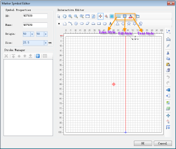
| Text |
Draw text:
- Click the Text button;
- In the symbol editing area, click the mouse at the target position to pop up the Set Text dialog;
- In the Set Text dialog, enter the text content, and you can also set the font, size, and font color. After setting, click the OK button to complete the drawing of a text. To draw another text, repeat the above steps.
- For versions prior to 12.0.1, text strokes are saved and stored according to their original type. Starting from version 12.0.1, to ensure correct display of text symbol positions, text strokes are by default converted to region strokes upon saving (this process is irreversible).
You can modify this default setting in the EnvironmentSetting.xml file located in the configuration folder of the installation package. Modify the parameter textConvertRegion, where a value of true means converting to a region stroke, and false means not converting.
|


 Tip:
Tip: