In the Marker Symbol Editor, to facilitate point symbol creation and editing, auxiliary tools such as rulers, background grids, and snapping functions are provided. Users can customize these tools to tailor the symbol editing environment according to their workflow requirements, collectively referred to as Symbol Editor Environment Settings. This section details how to configure the symbol editor environment.
Valid Range of Symbol Editing Area
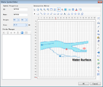
The valid range of the symbol editing area is demarcated by ruler markings. When drawn objects exceed this range, a warning "Symbol exceeds visible bounds:" will appear. As shown below, the grid-filled area represents the valid range. Only content drawn within this range constitutes valid elements of the point symbol.
 |
Marker Size vs. Display Size
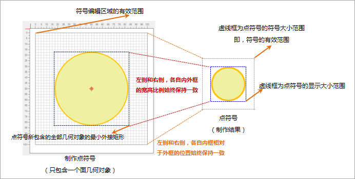
The valid range of the symbol editing area corresponds to the valid range of the created point symbol, as illustrated below. In practical applications, the displayed size of point symbols on maps is determined by setting marker size. Two size concepts exist:
- Display Size: Dimensions of the minimum bounds encompassing all geometries within the point symbol.
- Marker Size: Dimensions of the symbol's valid range.
- During symbol creation, the aspect ratio between the minimum bounds of all geometries (within valid range) and the valid range equals the aspect ratio between display size and marker size. Thus, setting marker size allows calculation of display size proportionally, and vice versa.
- The relative position relationship between the minimum bounds of all geometries (within valid range) and the valid range remains consistent regardless of symbol size changes.
If the minimum bounds of geometries coincide with the valid range, marker size equals display size. Typically, symbol creators and users differ. Users may not know the aspect ratio between geometries' bounds and valid range set by creators. The display size parameter provides convenience for users to directly control symbol content dimensions.
 |
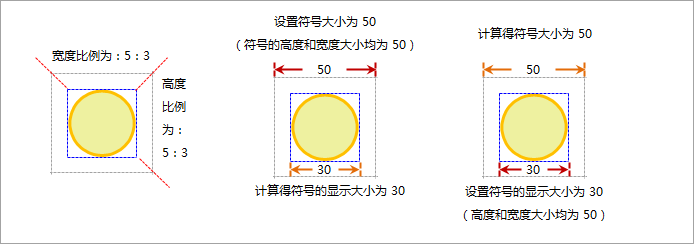
| Marker Size and Display Size Schematic Diagram |
When setting the marker size to 50 for the illustrated symbol (with valid range to geometries' bounds ratio as 5:3), the display size calculates to 30. Conversely, setting display size to 60 yields a marker size of 100.
 |
Background Settings for Symbol Editing Area
The default background of the symbol editing area is a grid aligned with ruler markings for precise positioning. Alternatively, images can be used as backgrounds to support vector-based symbol drawing.
- Click the Work Background Settings button to open the configuration dialog:
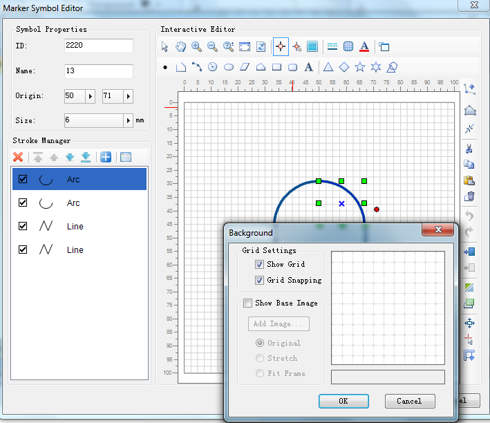
- Display Grid: Toggle grid visibility through checkbox selection.
- Show Raster Map: Activate to use raster images as backgrounds. Additional settings become available:
Add Image: Open file dialog to select background images.
Original Image: Maintains original image dimensions.
Stretch Map: Fills valid range by stretching image.
Adapt to Frame: Proportionally resizes image to fit valid range dimensions.
- Click OK to apply settings or Cancel to discard changes.
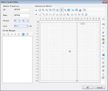
Ruler in Symbol Editing Area
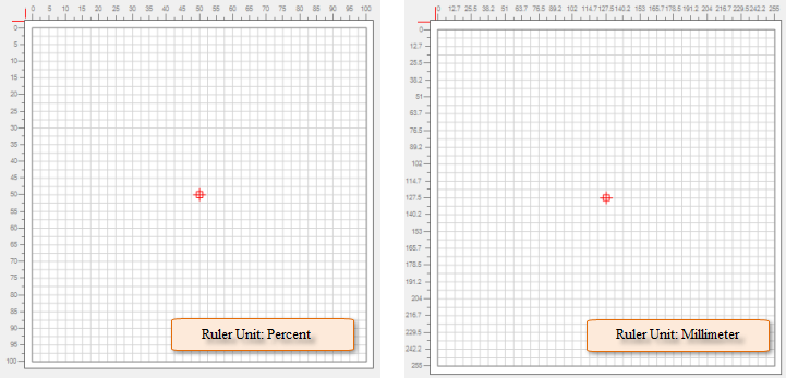
The ruler indicates the valid range and provides quantitative reference during editing, with percentage units.
 |
Snapping Settings
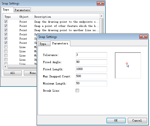
Snapping functionality ensures precise stroke relationships and cursor positioning. Two snapping types exist: stroke snapping and grid line snapping.
- Toggle snapping functionality using the Enable/Disable Snap button.
- When snapping is enabled, configure grid line snapping through the Snap Grid checkbox in Work Background Settings.
- Click Snapping Settings to configure snapping types and parameters:
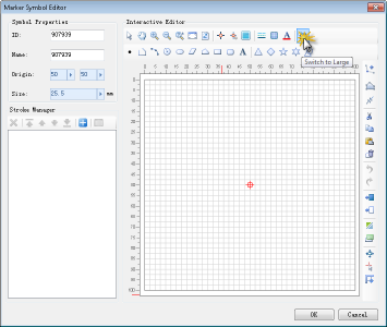
Full Screen Mode for Symbol Editing Area
Click Switch to Large Icons to enter full screen mode. Press ESC or click Return to Normal Mode to exit. Clicking any black area in full screen mode also returns to normal mode.