



Modify 3D Custom Thematic Map
Function Description
Users can modify various parameter settings of the 3D custom thematic map in the "Custom Thematic Map" window to achieve a more suitable thematic map effect.
Function Entry
- Layer Manager->3D Custom Thematic Map right-click menu->Modify Thematic Map... button
Operation Instructions
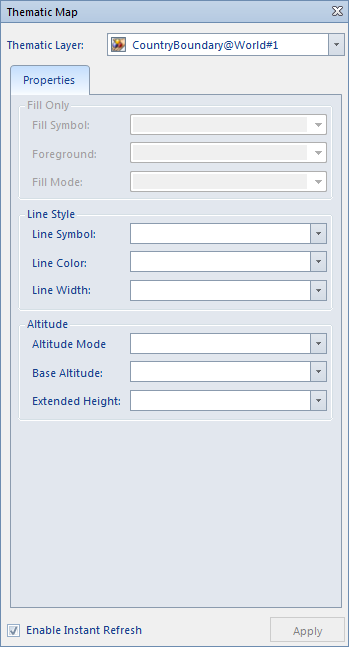
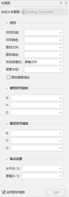
When creating 3D custom thematic maps based on area layers, line layers, and point layers respectively, the content displayed in the "Custom Thematic Map" window is shown in the figures below, with slight differences in settings.
 |
 |
|
| Create 3D Custom Thematic Map Based on Area/Line Layers | Create 3D Custom Thematic Map Based on Point Layer |
- In the Layer Manager, select a 3D custom thematic map layer, right-click and choose "Modify Thematic Map..." from the context menu. The "Custom Thematic Map" window will display the settings of the selected custom thematic map.
- Fill: Set the rendering style of area objects in the area layer.
- Fill Style: Select a numerical field or set an SQL expression, and render the object based on the value of the field or expression corresponding to the ID in the resource fill library. For example, after setting a fill style field, if an object's corresponding field value is 8, the system will search the resource fill library for the fill style with ID 8 and use that style to render the object. Note: Currently, the fill style of the custom thematic map only supports setting 3D symbols.
- Fill Foreground Color: Select a field expression for the foreground color of the fill symbol. The color (RGBA) is represented by a hexadecimal value, for example, the hexadecimal value of blue is #0000FFFF.
- Fill Mode: Select a numerical field or set an SQL expression. The system will select the corresponding fill mode based on the field value. If the field value is 1, it indicates area fill; if 2, outline fill; if 3, outline and area fill. If the field value is not 1, 2, or 3, the default value 1 is used, meaning area fill mode.
- Line: Set the rendering style of line symbols or extruded outlines, or the rendering style of boundaries of area objects in the area layer.
- Line Style: Select a numerical field or set an SQL expression, and render the object based on the value of the field or expression corresponding to the ID in the resource line library. For example, after setting a line style field, if an object's corresponding field value is 8, the system will search the resource line library for the line style with ID 8 and use that style to render the line object.
- Line Color: Select an attribute field (text type or 32-bit integer) or set an SQL expression, and set the color of the line style or extruded outline based on the field or expression value. The color (RGBA) is represented by a hexadecimal value, for example, the hexadecimal value of blue is #0000FFFF.
- Line Width: Select a numerical field or set an SQL expression, and set the width of the selected line style based on the field or expression value. The unit is 0.1mm.
- Material Name: Select an attribute field (text type) that records the path of the external material. If the external material is a PBR material, the line color will not take effect.
- Texture: Set the texture mapping mode.
- Repeat Mode: Supports two modes: actual size and repeat count.
- Horizontal Repeat: The texture is displayed according to the specified size or repeat count. When the repeat mode is repeat count, the horizontal size refers to the number of times the texture repeats horizontally, in times. When the repeat mode is repeat count, the horizontal size refers to the actual size of the texture horizontally, in meters.
- Vertical Repeat: The texture is displayed according to the specified size or repeat count. When the repeat mode is repeat count, the vertical size refers to the number of times the texture repeats vertically, in times. When the repeat mode is repeat count, the vertical size refers to the actual size of the texture vertically, in meters.
- Symbol: Set the rendering style of point objects in the point layer.
- Symbol Style: Select a numerical field or set an SQL expression, and render the object based on the value of the field or expression corresponding to the ID in the resource symbol library. For example, after setting a symbol style field, if an object's corresponding field value is 8, the system will search the resource symbol library for the symbol style with ID 8 and use that style to render the point object.
- Symbol Color: Select a numerical field or set an SQL expression, and set the color of the point model symbol based on the field or expression value. The color (RGBA) is represented by a hexadecimal value, for example, the hexadecimal value of blue is #0000FFFF.
- Icon File: Select a text field or set an SQL expression, and set the full path of the icon file (*.png, *.jpg, *.jpeg, *.bmp, *.gif, *.sgm, *.3ds, *.mesh, *.obj, *.dae, *.x, *.osg, *.osgb) based on the field or expression value. Note: When using an expression to specify the image path, double quotation marks in English format must be added.
- Icon Scale: Select a numerical field or set an SQL expression, and set the scaling ratio of the icon file based on the field or expression value.
- Billboard Mode: Select a numerical field or set an SQL expression, and set the landmark billboard mode based on the field or expression value. If the field value is 1, it indicates screen-aligned billboard; if 2, Z-axis aligned billboard; if 3, fixed rotation angle aligned billboard. If the field value is not 1, 2, or 3, the default value 1 is used, meaning screen-aligned billboard mode.
- Bend Radius: Select a numerical field or set an SQL expression, and set the bend radius based on the field or expression value.
- Icon Scale with Map: Used to set whether the icon scales with the map. It only takes effect when the icon file is in image format (*.png, *.jpg, *.jpeg, *.bmp, *.gif).
- Model Symbol Rotation: Select a numerical field whose value is used to specify the counterclockwise rotation angle of the 3D model symbol around the X, Y, or Z axis. Taking rotation around the Z axis as an example, the angle indicates the counterclockwise rotation from the north direction.
- Model Symbol Scale: Select a numerical field, and set the scaling ratio of the 3D model symbol along the X, Y, or Z axis based on the field value.
- Anchor Point Setting: Used to determine the placement position of the icon object by setting the relative position between the anchor point of the icon object and the 3D point in the custom thematic map.
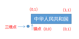
Figure: Schematic diagram of the relative position between the icon object anchor value and the 3D point - Horizontal (0-1): The relative position of the icon object to the 3D point in the horizontal direction. The value range is [0,1], where 0 means the leftmost horizontal edge of the icon outline is adjacent to the 3D point, and 1 means the rightmost horizontal edge of the icon outline is adjacent to the 3D point.
- Vertical (0-1): The relative position of the icon object to the 3D point in the vertical direction. The value range is [0,1], where 0 means the bottommost vertical edge of the icon outline is adjacent to the 3D point, and 1 means the topmost vertical edge of the icon outline is adjacent to the 3D point.
Notes
- When setting the transparency of area symbols, note that the transparency of the area fill symbol depends on the transparency set in the Fill Foreground Color field of the area object, not the transparency set in the Line Color of the area object's boundary.
- Creating a custom thematic map for a point layer supports not only 3D points but also composite points (EPS points).
- Custom thematic maps created and modified by users can be saved as templates for application in thematic map production of other layers.
- The values of fields and expressions correspond to the ID values of the symbol library. Taking the point symbol library as an example, open the workspace -> Symbol Library -> Fill Symbol Library. The method for viewing ID values is shown in the figure below:
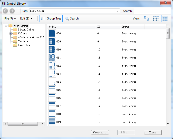
Figure: Point Symbol Library ID Viewing Window
Related Topics
Create a New 3D Custom Thematic Map
Create 3D Custom Thematic Map Based on Template