


Instructions for use
In 3D pipeline scenes, there are numerous different feature points, manholes, and ancillary facilities. To overcome the challenges of time-consuming, labor-intensive, and difficult-to-maintain manual modeling, SuperMap iDesktopX supports the creation of 3D adaptive pipe point symbols, 3D markers, and 3D line symbols, which can be saved in the symbol library for repeated use.
3D markers are used to represent wells and ancillary facilities such as valves and water meters. 3D line symbols are used to represent 3D pipelines. 3D adaptive pipe point symbols are used to represent feature points such as turning points, branching points, intersection points, diameter change points, elbows, and multi-way points.
New Adaptive Pipe Point Symbol
Relying on the topology of pipe points and pipelines in a 3D network dataset, 3D adaptive pipe point symbols can effectively resolve the matching issues between pipe points such as elbows and tees, and pipelines in the scene.
- In the "Workspace Manager", under "Resource", double-click "Marker Symbol Library" or right-click and select "Load Marker Symbol Library" to open the "Marker Symbol Selector" dialog;
- Click the "Edit" drop-down button, and in the "New Symbol" right-pull menu, select "New 3D Adaptive Symbol..." to open the "3D Adaptive Pipe Symbol Editor" dialog;
- Parameters
- End Thickness: Represents the length of the hoop of the pipe point symbol. When this parameter is set to "0", it means the symbol has no hoop;
- Corner Subdivision Count: Represents the smoothness of the elbow of the pipe point symbol. The larger the value, the smoother the elbow effect.
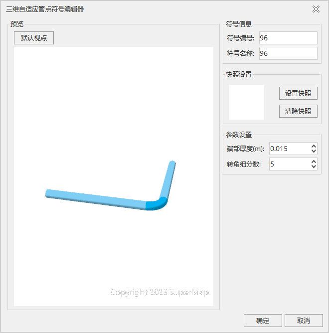
- After modifying the "Symbol Name" and setting the snapshot, click the "OK" button to complete the creation of the new 3D adaptive symbol.
New 3D Pipe Point Symbol
- In the "Workspace Manager", under "Resource", double-click "Marker Symbol Library" or right-click and select "Load Marker Symbol Library" to open the "Marker Symbol Selector" dialog;
- Click the "Edit" drop-down button, and in the "New Symbol" right-pull menu, select "New 3D Symbol" to open the "3D Marker Editor" dialog;
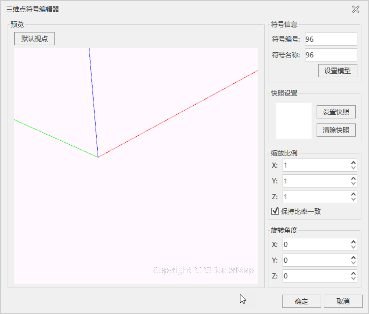
- Click the "Set Model" button, and the "Open" dialog will pop up. Select a custom model file (*.3ds/*.x/*.fbx/*.obj/*.stl/*.dae) and click "Open";
- Set the "Scale Factor" and "Rotation Angle"; you can use the default values;
- After modifying the "Symbol Name", click the "Set Snapshot" button to set the snapshot image for the symbol, then click "OK" to complete the creation of the new 3D marker.
New 3D Pipeline Symbol
- In the "Workspace Manager", under "Resource", double-click "Line Symbol Library" or right-click and select "Load Line Symbol Library" to open the "Line Symbol Selector" dialog;
- Click the "Edit" drop-down button, and in the "New Symbol" right-pull menu, select "New 3D Linear" to open the "3D Linear Symbol Editor" dialog;
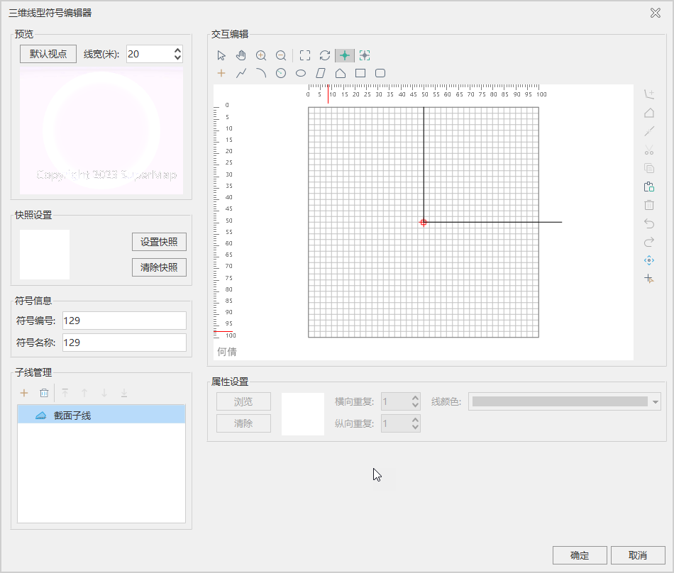
- In the "Cross-Section List", select a circular cross-section, set the "Line Width" and "Line Color", then modify the "Symbol Name" and other information;
- Click the "Set Snapshot" button to set the snapshot image, then click the "OK" button to complete the creation of the new 3D linear symbol.
Batch Build 3D Pipeline Symbols
Based on the pipeline cross-section information stored in a 3D line dataset, batch building 3D pipeline symbols improves the efficiency of creating 3D pipeline symbols and reduces manual intervention.
The attribute table of the 3D line dataset to be made into pipelines must have a property field for pipeline cross-section information, with a text type. For example, when the attribute value of the cross-section information is "30", it represents a circular pipe with a diameter of 0.03 meters; when it is "300X100", it represents a rectangular pipe with a length of 0.3 meters and a width of 0.1 meters, and the connector between 300 and 100 can be "X", "x", or "*".
- Under "Workspace" in "Resource", click the "Line Symbol Library" node. In the popped-up "Line Symbol Selector" window, click the "Build 3D Linear Symbols in Bulk" drop-down button, select the "Batch Build 3D Pipeline Symbols" option, and the "Create 3D Linear Symbols in Bulk" dialog will pop up, as shown below:
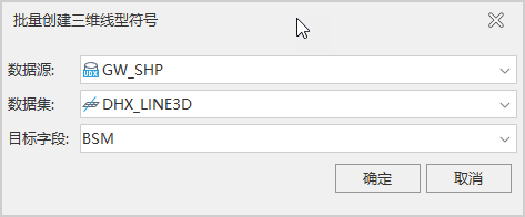
- Set Data Source: Select the data source where the 3D line dataset for which you need to create 3D linear symbols is located.
- Set Dataset: Select the 3D line dataset in that data source for which you need to create 3D linear symbols.
- Set Target Field: The property field that stores the pipeline cross-section information.
- After setting the above parameters, click "OK". Two property fields, SymbolID and LineWidth, will be automatically created in the attribute table of the 3D line dataset. The SymbolID attribute value stores the symbol ID of the automatically built 3D pipeline. For circular pipelines, the LineWidth attribute value stores the diameter of the pipeline cross-section in meters. For rectangular pipelines, the LineWidth attribute value stores the maximum value between the length and width of the pipeline cross-section in meters.
 Notes:
- The height mode and data source of the pipeline and pipe point layer settings must be consistent; otherwise, elevation inconsistencies may cause pipelines and pipe points not to display correctly.
- When creating line symbols using the "3D Linear Symbol Editor", if you are making pipelines with a circular cross-section, not checking the "Auto Break" option can improve rendering effects and performance.
- Although SuperMap GIS supports line symbol cross-sections of any shape, it is recommended to use left-right symmetric line symbols; otherwise, issues such as misalignment between pipelines and pipe points like elbows and tees may occur.