


Clipping
Usage Instructions
The oblique photogrammetry model clipping function enables clipping regions in oblique photogrammetry models. You can select or draw a polygon as the clipping area.
Function Entry
- 3D Geographic Design tab -> Oblique Photogrammetry Data operation -> Clipping button
- Toolbox -> 3D Data -> Oblique Data Operations -> Oblique Data Clipping
Operation Steps
- Create a new spherical scene. Right-click "Scene" in the workspace manager and select "New Spherical Scene".
- Load 3D tiles. In the layer manager, select "Normal Layer", right-click and choose "Add 3D Tile Layer", or on the Scene tab in the Data group, click the Tile drop-down button, and select "Load Tiles..." from the drop-down menu. For detailed operations, refer to the help document Load Tiles.
- In the layer manager, select the 3D tile file layer, right-click and choose "Quickly Locate to This Layer", then hold the mouse wheel in the scene window to adjust the camera to a perspective suitable for clipping the model.
- On the 3D Geographic Design tab in the Oblique Photogrammetry Operation group, click the Clipping button to pop up the "Oblique Photogrammetry Model Clipping" panel. The specific parameter settings are as follows:
- Layer Selection: Click the drop-down arrow on the combo box to the right of "Oblique Layer" to select the layer where the clipping object is located.
- Clipping Surface Determination: In the clipping surface group, two methods are provided: "Select Surface" and "Draw Surface".
- When "Select Surface" is selected, choose a surface object in the scene to complete the determination of the clipping surface. To select multiple surfaces for the operation, hold the Shift key and then select in the scene.
- When "Draw Surface" is selected, use the "Rectangle", "Polygon", and "Import" tools in the toolbar to determine the clipping surface.
- Click the "Rectangle" or "Polygon" tool, and after the mouse cursor is accompanied by a red dot, click the left button in the scene to start drawing the clipping area. Right-click to end the drawing and complete the determination of the clipping surface.
- Click the "Import" tool to pop up the import dialog box. Select a surface dataset or model dataset as the clipping area, as shown in the figure below.
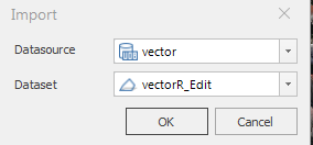
Figure: "Import" Dialog Box
- Export Clipping Surface: Supports exporting the drawn clipping surface by clicking the "Export" button.
- Parameter Settings:
- Click the drop-down arrow on the combo box to the right of "Clipping Boundary Elevation" and choose one of the two constraint methods: "Consistent with Original Data" or "Consistent with Clipping Surface". "Consistent with Original Data" means the elevation values of the clipping result boundary remain the same as the original, while "Consistent with Clipping Surface" means the elevation values of the clipping result boundary are consistent with those of the clipping surface boundary.
- Only when the constraint boundary is "Consistent with Original Data", the "Preview" checkbox is available. When the "Preview" checkbox is checked, you can preview the clipping result in real-time.
- Click "OK" to perform the clipping operation, and click "Undo" to revoke the clipping operation.
 Notes:
- When drawing the clipping area, it is recommended to view the scene from a top-down perspective to ensure the accuracy of the drawing points.
- When the clipping boundary elevation is set to "Consistent with Original Data", the Z-value of the clipping surface does not take effect.
- The oblique photogrammetry clipping operation also applies to model tiles, and supports viewing/rolling back historical records after operating on model tiles.