


Clip
Usage Instructions
The Oblique Photography Data Clipping function allows for custom clipping of oblique photography data by selecting or drawing a polygon as the clipping region.
This method enables users to easily obtain oblique photography data within a specific area based on their needs.
Function Entry
- 3D Geographic Design Tab -> Oblique Photography Data Operations -> Clip Button
- Toolbox -> 3D Data -> Oblique Data Operations -> Oblique Data Clipping
Operation Steps
- Create a spherical scene: Right-click "Scene" in the Workspace Manager and select "New Spherical Scene".
- Load 3D tiles: Select the general layer in the Layer Manager, right-click and choose "Add 3D Tile Layer", or on the Scene tab, in the Data group, click the Tile drop-down button and select Load Tiles... from the pop-up menu. For details, refer to the help documents Load Tiles or Tile Management.
- Select the 3D tile file layer in the Layer Manager, right-click Quickly Locate to This Layer, and adjust the camera to a view suitable for clipping the model by holding the mouse wheel in the scene window.
- On the 3D Geographic Design tab, in the Oblique Photography Data Operations group, click the Clip button to open the "Oblique Photography Data Clipping" panel.
- Layer Selection: Click the drop-down arrow on the right side of the "Oblique Photography Layer" combo box to select the layer containing the clipping target. This supports selecting local data or S3M tile data obtained from MongoDB database.
- Clipping Area Definition: Provides two methods: "Select Polygon" and "Draw Polygon".
- When "Select Polygon" is selected, click a polygon object in the scene to define the clipping area. To select multiple polygons for the operation, hold the Shift key while selecting in the scene.
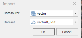
- When "Draw Polygon" is selected, use the "Rectangle", "Polygon", and "Import" tools in the toolbar to define the clipping area. Click the "Rectangle" or "Polygon" tool, the mouse cursor will display a red dot in the scene. Click to start drawing the area, right-click to finish drawing, completing the clipping area definition. Click the "Import" tool to open the Import dialog, select a polygon dataset as the clipping region, as shown below.
- Export Clipping Area: Supports exporting the drawn clipping area by clicking the "Export" button.
- Clipping Parameter Settings:
- Clipping Mode: Choose between "Keep Inside" or "Keep Outside". The "Keep Inside" mode clips to obtain the oblique photography data within the clipping region, while the "Keep Outside" mode clips to obtain the data outside the clipping region.
- Clipping Boundary Elevation: Choose between "Same as Original Data" or "Same as Clipping Polygon". "Same as Original Data" keeps the elevation values of the clipping result boundaries consistent with the original data; "Same as Clipping Polygon" makes the elevation values of the clipping result boundaries consistent with those of the clipping polygon boundaries.
- The "Preview" checkbox is selected by default, allowing real-time preview of the clipping result.
- Result Data Storage Settings:
- Click the file open icon on the right side of "Path" to select the storage path for the clipping result. You can also directly input the storage path in the text box.
- Enter the file name for storing the clipping result in the text box on the right side of "Target Name".
- Click "Save" to save the oblique photography data clipping result. An example result using the polygon clipping method is shown below.

 Note:
Note:- When the clipping boundary elevation is set to "Same as Original Data", the Z-value of the clipping polygon does not take effect.
- When drawing the clipping area, view the scene from a top-down perspective to ensure the accuracy of the drawn points.