Instructions for use
Used to cut into the surface of the earth in the scene and calculate the cut volume. Support multi-viewport excavation and support Import Export excavation surface.
Operation steps
- Before using the Polygon Excavation feature, set the appropriate area units. Area units are set in the same way as in the combo box on the right side of the Area Units tab in the Measurement group of the 3D Analysis tab. The specific operation is as follows:
- Click the Unit button in the Measurement group on the 3D Analysis tab to bring up the Unit Settings "dialog box. The user can select the required unit as the unit of Measure Area. The default area unit is: square meters.
- Turn on the Polygon Excavation feature. On the Scene tab, in the Underground group, click the Drop-down Button to the right of the On/Off tab, and select the On item to enable the Polygon Excavation feature. By default, the Polygon Excavation feature is turned off.
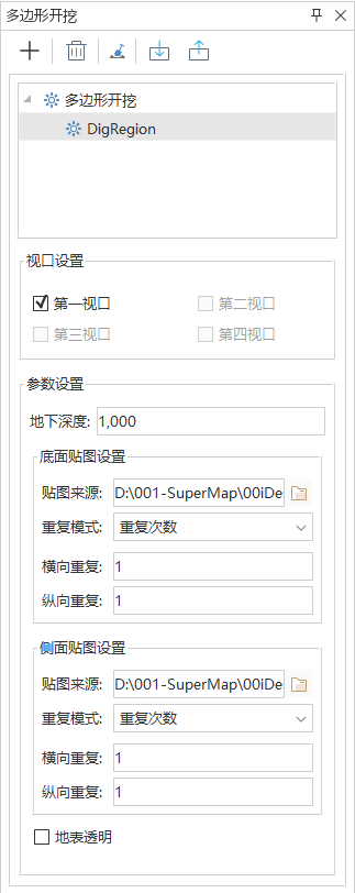
- Click the Excavation Drop-down Button and select Polygon Excavation from the drop-down menu. The Polygon Excavation "panel pops up. As shown in the figure.
 |
| Image: Polygon Excavation "Panel |
- Excavation surface determination: Click the Involved in Excavation "button, and Move Stop by Mouse into the Scene, then the mouse status changes to
 the status, and the Surface Area to be excavated can be drawn on the earth surface in the Scene.
- Click the left mouse button continuously at the appropriate position, and Draw Polygon to delineate the excavation range to be measured. After two or more nodes of the polygon are determined, move the mouse, and the current mouse point and the determined points can form a temporary region, which changes with the movement of the mouse. Click the right mouse button to end the drawing.
- After the excavation surface is drawn, a corresponding node is added to the excavation surface list in the panel.
- Click the editable button in front of the corresponding excavation to perform Parameter Settings on the panel.
- Depth: Set visible depth. Underground objects with a depth greater than this value will not be displayed.
- Side Texture Settings: Used to set the picture source, repeat mode, horizontal/vertical Repeat Times, or size of the Side Texture after excavation. Populated by default with the Installation Path \ Bin \ Resource \ excavation region _ side. JPG.
- Bottom Texture Settings: Used to set the image source, repeat mode, horizontal/vertical Repeat Times, or size of the map of the bottom surface after excavation. Populated by default with the Installation Path \ Bin \ Resource \ excavation region _ top. JPG.
- Transparent Surface: Used to set whether the excavation area uses the default Picture Fill or Transparent Display. When the "Transparent Surface" "check box is checked, the Fill Settings parameter is unavailable, which means that no filling is used and the excavation area is Transparent Display; When the Transparent Surface "check box is not selected, the cut area is filled and displayed using the parameters set in the dialog.
- OSGB Layer Involved in Excavation: Used to set whether the Oblique Photography layer in the scene participates in the Surface Excavation operation. Selecting this button indicates that the Oblique Photography layer in the scene will be excavated; deselecting this button indicates that if there is an Oblique Photography layer in the scene, it will not be excavated during Surface Excavation.
- When the camera height is positive (it is required to be visible when the camera height is less than 10 km), the underground effect is visible within the area. The Polygon Excavation area is also displayed in the Output Window by clicking on the selected excavation face.
- If it is necessary to continue with the Polygon Excavation, repeat steps 1 through 7.
- Clicking the Delete Node "in the panel deletes the currently selected Surface Excavation face.
- Click the "Clear"
 button to clear the results of all cut areas in the current Scene. Meanwhile, when the camera height is a positive value, the underground effect within the scope of the "Polygon Excavation" "area is invisible.
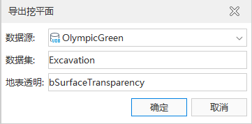
- Export: Click the Export button. The Export Excavation Face dialog box pops up, as shown in the figure. Select the Datasource of the excavation face and name the Dataset. The Dataset is named Excavation by default and can be customized.
 |
| Figure: Export Cut Faces Dialog Box |
- Import: Click the Import button. The Import Excavation Face dialog box pops up, as shown in the figure. Sets the Property Field. For Datasource, Dataset, and landmark transparency of the imported cut face.
 |
| Figure: Import Cut Face dialog box |
 Precautions
- In conjunction with the viewport mode in View Management in the Scene tab, you can select excavation viewports in the View Port Settings area of the panel to achieve multi-viewport excavation.
- In case of OSGB Layer Involved in Excavation, the problem that the excavation surface cannot be selected directly may be solved by hiding the Oblique Photography layer and selecting it again or offsetting the excavation surface layer.
 the status, and the Surface Area to be excavated can be drawn on the earth surface in the Scene.
 button to clear the results of all cut areas in the current Scene. Meanwhile, when the camera height is a positive value, the underground effect within the scope of the "Polygon Excavation" "area is invisible.


 Precautions


