Usage
Currently, many projects often use 3ds Max and other modeling software for pipe well modeling, but this method incurs high work time and labor costs when constructing large volumes of pipe well models. To address this, the Pipe Well Modeling function provides a method to quickly batch-build pipe well models based on original pipeline data and specified rules.
Before pipe well modeling, the name prefixes of raw pipeline data of the same type must remain consistent. Taking the "water pipe" data as an example, SSG is the initial abbreviation of "water pipe" in Chinese. "SSG_POINT" represents water pipe point data, "SSG_LINE" represents water pipe line data, and "SSG_BOUNDLINE" represents water pipe polygon data. The point, line, and polygon data must have corresponding attribute fields. The point data records the location, shape, and material of the pipe well; the line data records the location of the pipeline; and the polygon data records the extent and location of the well chamber. Still using the water pipe as an example, the parameters for each type of data are shown in Table 1:
| Name | Stored Information | Attribute Field Type |
|---|---|---|
| SSG_POINT | Location, shape, material of the pipe well | Pipe well ID, elevation, well depth, neck depth, cover shape, cover length, cover material, cover width, rotation angle, cover diameter, chamber diameter, chamber code, chamber ID code, well material, chamber polygon association ID, well thickness, and bottom groove diameter |
| SSG_LINE | Location of the pipeline | QDGC (start elevation), ZDGC (end elevation) |
| SSG_BOUNDLINE | Shape and material of the well chamber polygon | Chamber polygon association ID |
Function Entry
- 3D Geographical Design tab -> Model Operation group -> Procedural Modeling drop-down menu -> Pipe Well Modeling
Operation Steps
- In the workspace manager, open the datasource containing the original 2D point, line, and polygon datasets (projected coordinate system).
- Click Pipe Well Modeling in the Rule Modeling group of the 3D Geographical Design tab to open the "Pipe Well Modeling" dialog. Set the corresponding parameters based on the actual data conditions.
- Set source datasets: Use the Add, Select All, Invert Selection, Delete, etc. buttons on the toolbar to set the datasets involved in the operation.
- Add: In the pop-up selection dialog, select the 2D point, line, and polygon datasets to be processed. After selection, click OK. The data list will display the point dataset, associated line dataset, and associated polygon dataset lists. The point, line, and polygon datasets are associated via the dataset name prefix.
- Select All: Select all datasets in the data list.
- Invert Selection: Select the datasets that are not selected in the data list.
- Delete: Remove the dataset from the current data list.
- Mapping setting for pipe well modeling field values: Use the "Mapping Setting" button on the toolbar to configure the correspondence between attribute field values and modeling rules, achieving standardized conversion of attribute values.
- Mapping Field: Select the field to be mapped from the drop-down list, including cover shape, well material, and pipe well ID.
- Mapping Rule: Enter the mapping relationship in the input box following the format attribute field value = modeling rule.For example, select the "Cover Shape" field, whose values are 0 or 1, and map as: 0=Rectangle, 1=Circle. Click Apply, and the system will save the current mapping and display it in the rule preview box.
- After setting, click OK to complete the mapping setting.
- Set basic parameters:
- Pipe Well ID (required): Set the pipe well type, e.g., rain grate well, inspection well, valve well, etc., used to distinguish the type of texture map referenced by the well cover model. Set by selecting an attribute field in the point dataset; field type is wide character. If this attribute is empty, the point is not a pipe well.
- Elevation (required): The elevation of the highest point of the pipe well, i.e., the elevation of the center point of the well cover, in meters. Set by selecting an attribute field in the point dataset; field type is double precision.
- Well Depth (required): The total depth of the pipe well, i.e., the vertical distance from the top of the well cover to the bottom of the well chamber, in meters. Set by selecting an attribute field in the point dataset; field type is double precision.
- Neck Depth (required): The height of the well neck, in meters. Set by selecting an attribute field in the point dataset; field type is double precision.
- Material Folder Path (required): Set the path for the texture maps required when constructing the pipe well model by specifying a path.
 Notes:
During modeling, based on the well cover shape attribute value and the pipe well ID attribute value, the system will look for the texture map of the well cover model in the "Material Folder Path". To ensure modeling quality, it is recommended that the texture map naming for the well cover model follows these rules:
- For well covers without shape differentiation, the texture map name should be consistent with the pipe well ID name, e.g., rainwater well.
- For well covers with shape differentiation, the texture map naming format is: well cover shape_pipe well ID. The specific rules are as follows:
- When the well cover size (shape) field value is Rectangle, Round, or Rectangular, the texture map name should be like Rectangular_RainwaterWell or Round_RainwaterWell.
- When the well cover size (shape) field value is a numeric value, numeric value*numeric value, numeric valueXnumeric value, or numeric valuexnumeric value, the texture map name should be shape corresponding to the numeric value_pipe well ID, e.g., 1200*2700, the texture map name is Rectangular_RainwaterWell.
- Target Datasource: Set the datasource for saving the result dataset by creating a new datasource or selecting an existing one.
- Set well cover parameter fields:
- Unit Setting (optional): Select the unit corresponding to the well cover parameter field values (except rotation angle) from the drop-down list, including millimeters, centimeters, decimeters, meters, inches, feet. The default value is millimeters.
- Well Cover Size (Shape) (required): Set the well cover shape. Set by selecting an attribute field in the point dataset; field type is wide character. The attribute field value can be "Rectangle", "Rectangular", "Square", "Round", "0", "1", or a numeric value, numeric value*numeric value, numeric valueXnumeric value, numeric valuexnumeric value.
- When the field value is "Rectangle", "Rectangular", "Square", or "0", the well cover length and well cover width parameters need to be set to construct a rectangular well cover.
- When the field value is "Round" or "1", the well cover diameter needs to be set to construct a circular well cover.
- When the field value is a single numeric value, e.g., the field value is 700 and the unit is set to millimeters, a circular well cover with a diameter of 700 mm will be constructed.
- When the field value is numeric value*numeric value, numeric valueXnumeric value, or numeric valuexnumeric value, e.g., the field value is 2700X1200 and the unit is set to millimeters, a rectangular well cover with a length of 2700 mm and a width of 1200 mm will be constructed.
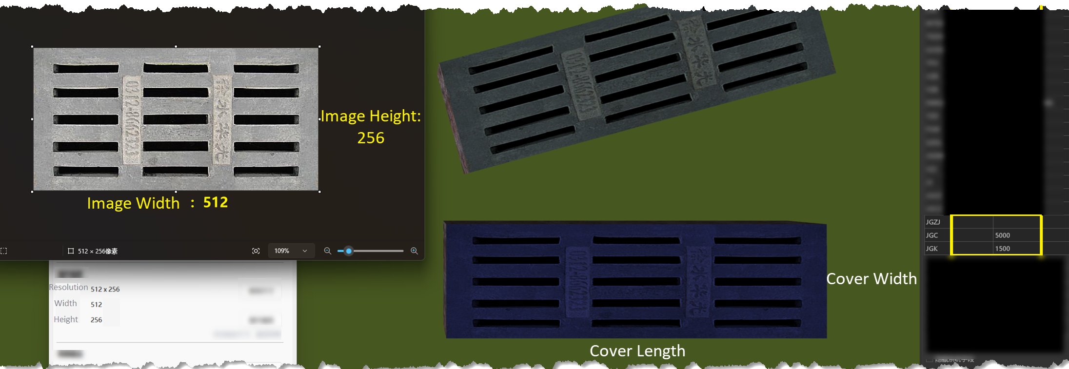
- Well Cover Length (conditionally required): When the well cover shape is rectangular, the well cover length must be set. Set by selecting an attribute field in the source point dataset; field type is double precision.
- Well Cover Width (conditionally required): When the well cover shape is rectangular, the well cover width must be set. Set by selecting an attribute field in the source point dataset; field type is double precision.
The correspondence between the width and height of the well cover material image and the well cover length and well cover width parameters is shown in the figure below.
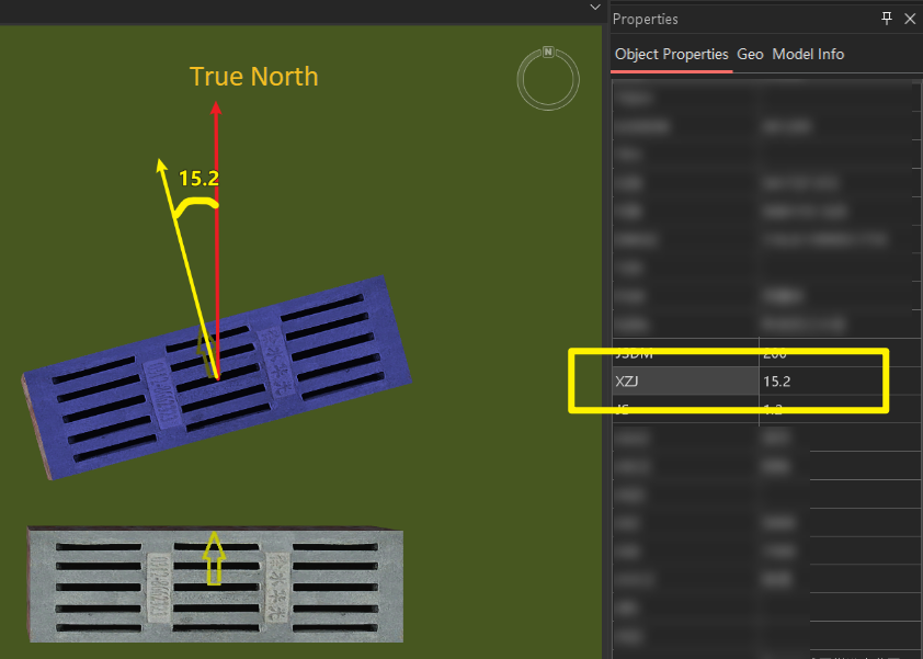
- Rotation Angle (conditionally required): When the well cover shape is rectangular, the rotation angle of the well cover must be set (with the center of the well cover as the rotation point, true north as the 0-degree reference direction, rotating counterclockwise), in degrees. Set by selecting an attribute field in the point dataset; field type is double precision.
- Well Cover Diameter (conditionally required): When the well cover shape is circular, the well cover diameter must be set. Set by selecting an attribute field in the point dataset; field type is double precision.
- Set well neck parameter fields:
- Neck Depth: Used to set the depth of the well neck (unit: meters). You need to select a double precision field from the source point dataset as the value source.
- Neck Type: Used to set the structure type of the well neck (reducing type or straight cylinder type). You need to select a text field from the source point dataset as the type source. Only when both the well cover and the well chamber are circular can either type be selected; otherwise, only the straight cylinder type is supported.
- Set well chamber parameter fields:
- Unit Setting (optional): Select the unit corresponding to the well chamber size (diameter), well chamber length, well chamber width, well thickness, bottom groove diameter and other well parameter field values from the drop-down list, including millimeters, centimeters, decimeters, meters, inches, feet. The default value is millimeters.
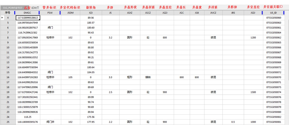
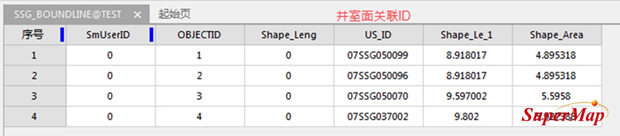
- Well Chamber Polygon Association ID (required): Set by selecting an attribute field that exists in both the source point dataset and the source polygon dataset with the same name; field type is wide character. The figure below shows the chamber polygon association ID in the attributes of the point and polygon datasets. The system first obtains the corresponding field value from the point dataset, then finds the same field value in the corresponding polygon dataset, and uses the polygon corresponding to that field value as the cross-section of the well chamber.
- Well Chamber Size (Diameter) (required): Set the size of the cross-section of the well chamber. Set by selecting an attribute field in the source point dataset; field type is wide character. The attribute field value can be expressed as a numeric value, numeric value*numeric value, numeric valueXnumeric value, or numeric valuexnumeric value.
- For the same well chamber, the "Well Chamber Size (Diameter)" parameter is mutually exclusive with the "Well Chamber Length" and "Well Chamber Width" parameters.
- When the "Well Chamber Size (Diameter)" attribute value is in the form of a numeric value, it indicates that the cross-section shape of the well chamber is circular, and the attribute value is the diameter of the circle.
- When the "Well Chamber Size (Diameter)" attribute value is in the form of numeric value*numeric value, numeric valueXnumeric value, or numeric valuexnumeric value, it indicates that the cross-section shape of the well chamber is rectangular, and the attribute values are the length and width of the rectangle.
- Well Chamber Length (required): Set the length of the cross-section of the well chamber. Set by selecting an attribute field in the point dataset; field type is double precision.
- Well Chamber Width (required): Set the width of the cross-section of the well chamber. Set by selecting an attribute field in the point dataset; field type is double precision.
- Rotation Angle (required): When the cross-section shape of the well chamber is rectangular, the rotation angle of the well chamber must be set (with the center of the well chamber as the rotation point, true north as the 0-degree reference direction, rotating counterclockwise), in degrees. Set by selecting an attribute field in the point dataset; field type is double precision.
- Well Material (conditionally required): When the Pipe Well ID field in the point dataset has a value, the well material must be set. Set by selecting an attribute field in the point dataset; field type is wide character. For example, if the specified field value is brick-concrete, the system will search for a texture map file named brick-concrete (e.g., brick-concrete.jpg) in the specified Material Folder Path as the texture map for the well chamber model.
- Well Thickness (optional): Set the wall thickness of the pipe well. Set by selecting an attribute field in the point dataset; field type is double precision or text.
- Bottom Groove Diameter (optional): The bottom groove is a "U-shaped" device built from masonry or poured concrete for purposes such as material transfer, sewage discharge, and drainage during well construction. If a groove needs to be constructed at the bottom of the pipe well, this parameter can be set. Set by selecting an attribute field in the point dataset; field type is double precision or text.
- Well Chamber Code (required): Select an attribute field in the point dataset used to identify the type of well chamber; field type is wide character. The value of this field will determine whether the well chamber belongs to "one chamber with multiple wells" or "one chamber with one well".
- Well Chamber Code Identifier (required): Specify the specific value in the "Well Chamber Code" field that represents "one chamber with multiple wells". If the selected field value equals this identifier, the well chamber is treated as "one chamber with multiple wells" (the well chamber and well are processed as a single unit); otherwise, it is treated as "one chamber with one well". The default identifier for one chamber with multiple wells is 202.
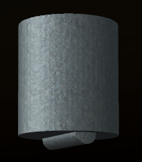
- After the settings are complete, click OK to execute the operation. The system will construct the corresponding pipe well model based on the point and polygon datasets with the same name. For example, SSG_POINT and SSG_BOUNDLINE form SSG_TubeWell, and then based on the elevation information in the 2D line attributes, they are converted into 3D lines. For example, SSG_LINE is converted to SSG_LINE3D. The composition of the pipe well model is shown in the figure below: 1 represents the well cover, 2 represents the well neck, 3 represents the well chamber, and 4 represents the entire pipe well.

- In addition, some pipe wells may also have ancillary devices such as grooves, as shown in the figure below: