Linear Extrusion
Instructions
Linear Extrusion enables rapid creation of 3D models from 2D or 3D polygon data through extrusion-based modeling operations.
This function is applicable to 2D polygon datasets and 3D polygon datasets. During extrusion modeling, the platform can read a specific attribute field from the polygon layer as the parameter value for extrusion height, X-direction scaling, and Y-direction scaling, enabling quick creation of 3D models with various shapes.
Function Entrances
- 3D Geographic Design Tab -> Regular Modeling Group -> Parametric Modeling Drop-down Menu -> Linear Extrusion
- Toolbox -> 3D Data -> Regular Modeling -> Linear Extrusion
Operational Steps
- Right-click "Datasource" in the Workspace Manager, select "Open File Datasource," and open the datasource containing the 2D/3D polygon dataset to be operated on.
- Select the polygon dataset to be operated on, right-click and select "Add to New Scene," then select the polygon dataset layer in the Layer Manager, and right-click "Locate to This Layer."
- Click the Extrusion drop-down button in the Regular Modeling group on the 3D Geographic Design Tab. In the pop-up drop-down menu, click the Linear Extrusion button to open the "Linear Extrusion" panel.
- Source Data Settings
- Datasource: Select the datasource containing the 2D or 3D polygon dataset to be operated on.
- Dataset: Select the 2D or 3D polygon dataset to be operated on.
- Operate on Selected Objects Only: When the layer is added to the scene and a polygon object is selected in the scene, checking this box allows the linear extrusion operation to be performed only on the selected object.
- Parameter Settings: Set parameters for linear extrusion.
- Extrusion Height: Set the height value for polygon extrusion by directly entering a numerical value or clicking the button next to the parameter to select an attribute field.
- Bottom Elevation: Set the bottom elevation value for the resulting model object by directly entering a numerical value or clicking the button next to the parameter to select an attribute field.
- X Scaling: Set the scaling ratio of the source polygon data in the X direction. The default value is 1.
- Y Scaling: Set the scaling ratio of the source polygon data in the Y direction. The default value is 1.
- Rotation Angle: Set the angle by which the top surface of the extruded object rotates counterclockwise around its central axis. The parameter range is [0,360], the unit is degrees, and the default value is 0.
- Material Settings: Available only after checking "Texture Coordinates." Used to set the material texture for the resulting model object.
- Object Type: Available only when the "Split Objects" checkbox is selected. Used to select the model sub-object for material setting, including Top, Side, and Bottom.
- Material Settings: Set the name and color of the material for the specified object. Currently, material color can be set by specifying a color via the color palette or selecting an attribute field that records the material color.
- Texture Settings: Set the texture map by directly selecting a texture image file (*.png/*.jpg/*.jpeg/*.bmp) or selecting an attribute field that records the texture storage path.
- Texture Repeat: Set the actual size of the texture map by specifying the repeat mode and horizontal/vertical dimensions. When the repeat mode is "Actual Size," the texture is laid on the model surface with the specified dimensions. Horizontal Repeat and Vertical Repeat are used to set the actual width and height of the texture map, in meters. When the repeat mode is "Repeat Count," the texture is laid on the model surface for the specified number of times. Horizontal Repeat and Vertical Repeat are used to set the number of repetitions in the horizontal (U) and vertical (V) directions, in times.
- Split Objects: Used to set whether to split the extruded model object into three sub-objects: Bottom, Top, and Side.
- Texture Coordinates: Used to set whether to apply texture mapping based on texture coordinates.
- With LOD: Used to set whether the extruded model includes LOD.
- Result Data Settings:
- Datasource: Select the datasource for storing the resulting model dataset.
- Dataset: Set the name of the resulting dataset by entering a string.
- After completing the parameter settings, click the "OK" button to execute the linear extrusion operation. A model dataset named after the specified dataset will be generated under the specified result datasource.
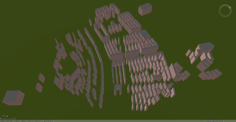
The image below shows a building model created through extrusion modeling.