


Urban Road Design
Instructions
The Urban Road Design function can quickly construct urban road and intersection models based on the original dataset (network dataset is optimal) and related parameter information.
This function currently only supports use in the Windows operating system.
Function Entry
- 3D Geographic Design tab -> Rule-Based Modeling group - > Procedural Modeling dropdown menu -> Urban Road Design button
Operation Steps
- In the workspace manager, open the target data source containing the original dataset (network dataset is optimal), and create or open an existing scene. Note: The original dataset must contain a road grade (or road type) field, a road name (or other road identification information) field, and the field type must be text.
- Click the Urban Road Design button in the Procedural Modeling dropdown menu within the Rule-Based Modeling group of the 3D Geographic Design tab.
- In the "Project Path Settings" dialog box that pops up, customize the storage path for the urban road design project. The default is C:\SUModelingWorkDir. After setting, click OK to open the Urban Road Design tab.
- Set road rules: Click the Road Style button in the Project Management group under the Urban Road Design tab. In the road style panel that pops up, set the road design rules. If the default rules are suitable for the existing data, you can skip directly to step 5.
- The panel lists all road styles, which must include the corresponding field values of the road styles in the original dataset.
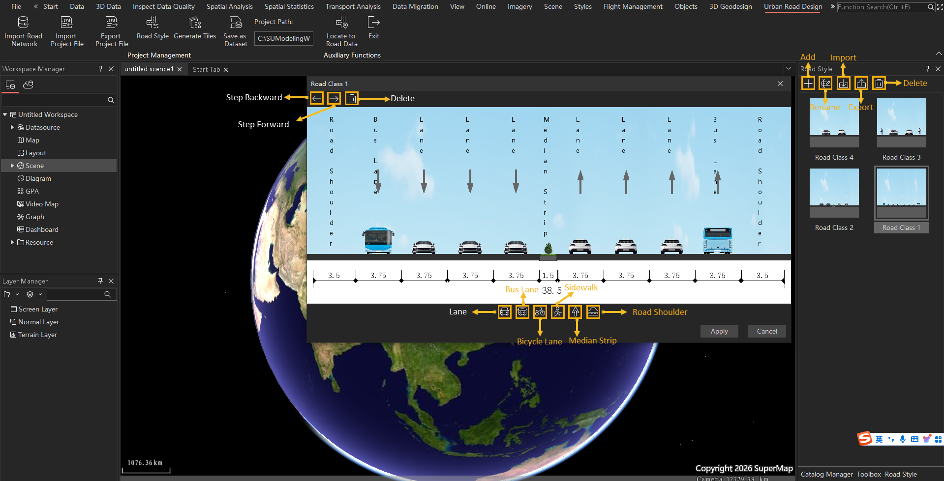
- The panel toolbar provides New, Import, Export, and Delete buttons.
- New: Add a road style with a specified name.
- Rename: Rename a specified road style.
- Import: Select a specified road rule file (*.xml) to import into the program.
- Export: Export all road styles contained in the panel as a road rule file (*.xml) to a specified path.
- Delete: Delete the selected road style.
- After double-clicking a road style, a dialog box will pop up, listing all road elements included in that road style, including lanes, bus lanes, non-motor vehicle lanes, sidewalks, shoulders, and central medians.
- The dialog toolbar provides Undo, Redo, and Delete buttons. The Undo button is used to undo the previous single operation. The Redo button is used to redo the previous single operation. The Delete button is used to delete the road element selected in the preview page.
- At the bottom of the dialog, there are road element buttons. By directly dragging an element to the preview page of the dialog, the element can be added. After selecting an element in the preview page, you can change the element arrangement by directly dragging it.
- Double-click a specific element in the preview page to adjust element attribute values in the Lane Properties dialog box, including road type, road width, direction, stop line, guide arrows, etc.
- Road type setting: Select the road type from the dropdown menu on the right.
- Road width: Set the road width by directly entering a value, in meters.
- Direction: Select the road direction, including Front and Back. Front means the direction facing into the screen, Back means the direction facing out of the screen.
- Stop line: Set whether to have a stop line and its thickness, in meters.
- Guide arrows: Set whether to have guide arrows and their initial distance and step length. The initial distance can be used to set the distance of the guide arrow from the stop line, in meters. The step length can be used to set the interval distance between guide arrows, in meters.
- The panel lists all road styles, which must include the corresponding field values of the road styles in the original dataset.
- Import road network data: Click the Import Road Network button in the Project Management group under the Urban Road Design tab. The "Import Road Network Data" dialog box will pop up. The specific operations are as follows:
- Data source: Click the dropdown button on the right to select the data source of the source network dataset.
- Dataset: Click the dropdown button on the right to select the target network dataset.
- Road style: Click the dropdown button on the right to select the field representing the road style.
- Road name: Click the dropdown button on the right to select the field representing the road name.
- After setting, click OK.
- After the settings are completed, the original dataset will be loaded in the scene, and urban roads will be built according to the road rules.
- If needed, you can make road detail adjustments. Select a specific road and then choose Edit from the right-click menu. The Road Editing panel will list the road elements contained in that road.
- Toolbar: The toolbar provides Add, Move Up, Move Down, and Delete buttons for adding, sorting, and deleting road elements.
- Basic properties: Set the road type and road width. Set the road type via the dropdown menu and the road width by directly entering a value, in meters.
- Lane properties: Set the lane direction by checking the radio button to set the road direction as Front or Back.
- Stop line: Set the thickness of the stop line, in meters. After checking the Stop Line checkbox, directly enter a value in the Thickness dialog.
- Guide arrows: Set the initial distance and step length of the guide arrows. After checking the Guide Arrows checkbox, directly enter a value in the Initial Distance dialog to set the distance of the guide arrow from the stop line; directly enter a value in the Step Length dialog to set the interval distance between guide arrows.
- Import project file: Click the Import Project File button in the Project Management group under the Urban Road Design tab to open an existing urban road design configuration file (*.srd) in the current scene.
- Export project file: Click the Export Project File button in the Project Management group under the Urban Road Design tab to export the design results in the current scene as an urban road design configuration file (*.srd) and save it with a specified file name at a specified path. The urban road design configuration file will record the design content in the current scene.
- Save as dataset: Click the Save as Dataset button in the Project Management group under the Urban Road Design tab to save the design results to a specified data source.
- Data source: Select a data source from the workspace via the dropdown menu to save the result dataset, or create a new data source at a specified path to save the result dataset.
- Save model: Set whether to save the design results as corresponding model datasets, such as road, median strip, motor vehicle lane, non-motor vehicle lane, crosswalk model datasets, etc. Checked by default.
- Save vector: Set whether to save the design results as corresponding vector datasets, such as road centerlines saved as 3D line datasets, median strips, crosswalks saved as 3D area datasets, etc. Checked by default.
- Generate tiles: Click the Generate Tiles button in the Project Management group under the Urban Road Design tab to generate the design results as S3M tile data in the project path.
 Note:
Note:The spatial reference of the result data depends on the source data: if the source data is in a projected coordinate system, the result data will be planar coordinates without spatial reference; if the source data is in a geographic coordinate system, the result data will uniformly adopt the WGS 84 coordinate system (EPSG:4326).
- Auxiliary functions:
- Locate road network data: Click the Locate Road Network Data button in the Auxiliary Functions group under the Urban Road Design tab to display a panoramic view of the current design results.
- Exit: Click the Exit button in the Auxiliary Functions group under the Urban Road Design tab to exit the urban road design process.