


Instructions
The scene beautification function supports replacing the material of S3M tiles (only Rendering Engine V2), achieving beautification at the data level; it also supports batch adding vegetation or static models in the scene.
 Notes:
To ensure the successful replacement of S3M tile materials, the material type of the target tiles must be UE material; otherwise, the operation will be invalid. Therefore, it is recommended to explicitly specify the material type as "UE Material" in the data beautification parameter settings when initially generating S3M tiles through the Model Dataset to Tiles, Merge to Generate Model Tiles, or Extrude Polygons to Generate Model Tiles functions or tools.
Through the scene beautification function, you can open the Asset Manager. The Asset Manager supports viewing and editing materials, vegetation, or static models.
- Material: By clicking the Material button in the Asset Manager, you can access the built-in material library (storage path: SuperMap iDesktopX installation path\templates\Materials), including PBR (Physically Based Rendering) materials such as concrete, masonry, metal, plastic, and stone. To use additional material assets in the software, place them in the same path as the default materials. More material assets (extraction code: smsw) can be accessed by clicking the blue text.
- Vegetation: By clicking the Vegetation button in the Asset Manager, you can access the built-in vegetation asset library (storage path: SuperMap iDesktopX installation path\templates\Assets\Plant\Examples), including Plane trees, Birch trees, etc. To use additional vegetation assets in the software, place them in the same path as the default vegetation assets. More vegetation assets (extraction code: smsw) can be accessed by clicking the blue text.
- Static Model: By clicking the Static Model button in the Asset Manager, you can access the built-in model asset library (storage path: SuperMap iDesktopX installation path\templates\Assets\Asset), including characters, urban plot accessories, sports facilities, road accessories, etc. To use additional assets in the software, place them in the same path as the default static models. More static model assets (extraction code: smsw) can be accessed by clicking the blue text.
Function Entry
- Scene Tab -> Scene Beautification Group -> Scene Beautification Button
Operation Steps
Replace Material
- Open a scene or create a new scene, open the S3M tile data to be operated on, select the model dataset layer in the Layer Manager, right-click and choose Quick Locate to This Layer.
- Click the Scene Beautification button in the Scene Beautification group under the Scene tab. The "Asset Manager" dialog box will appear at the bottom of the current window. Select "Material" in the dialog box to display the built-in material assets.
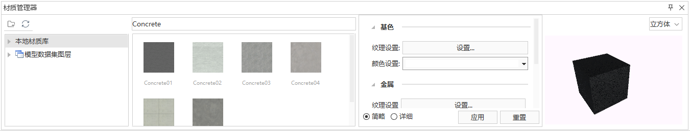
- The Asset Manager includes the toolbar, material library list, and material list.
- Toolbar: Provides back, refresh, and search functions.
- Back: Allows returning from the current list to the parent menu.
- Refresh: Refreshes the content in the current material library list.
- Search: Enter an asset name in the text box at the upper right of the specific material list to display only relevant materials in the current material list.
- Material Library List: Displays the built-in PBR materials such as Concrete, Masonry, Metal, and Stone.
- Material List: Displays all materials in the currently selected material library, and also supports previewing the effect of materials after parameter adjustments.
- Right-click a specific material to perform operations such as copy, rename, open containing folder, and delete.
- Copy: Copies the current material texture to the clipboard.
- Rename: Modifies the name of the currently selected material file.
- Open Containing Folder: Opens the folder where the currently selected material is located.
- Delete: Deletes the currently selected material file from the current material library.
- Right-click a blank area in the material list to create new, paste, and open folder operations.
- New: Creates a new PBR material in the current material library.
- Paste: Pastes the previously copied material into the current material library.
- Open Folder: Opens the folder where the current material library is located.
- The right-click menu of the material library node provides rename and delete folder functions.
- Rename: Sets a new name for the currently selected material library.
- Delete Folder: Deletes the local folder corresponding to the currently selected material library.
- Toolbar: Provides back, refresh, and search functions.
- Material Editing: Through the asset editing panel, you can adjust and save various parameters of the selected material.
- Color Adjustment
- Brightness: Adjust the overall lightness or darkness of the material by dragging the slider or entering a value. This parameter controls the brightness offset of the material, with a range of [-100.0, 100.0] and a default value of 0.0. Positive values make the material brighter, negative values darker.
- Contrast: Adjust the difference between light and dark areas. The higher the value, the more pronounced the contrast between bright and dark areas. This parameter controls the contrast strength of the material, with a range of [-100.0, 100.0] and a default value of 0.0. Positive values increase contrast (brighter brights, darker darks), negative values decrease contrast (grayer image).
- Saturation: Controls the vividness of the material's color. The lower the value, the closer the color is to grayscale. This parameter defines color purity, with a range of [-100.0, 100.0] and a default value of 0.0. Positive values increase saturation, making colors more intense; negative values decrease saturation, trending toward black and white.
- BaseColor Adjustment
- Texture Settings: Sets the texture map file representing the object's surface color. Click the texture image to open the "Asset Editor" dialog box, where you can edit the texture image source (replace, delete, export), texture offset/rotation/scale, etc.
- Base Color: Sets the object's surface color. Click the dropdown menu to open the color picker and specify a color.
- Translation: Enables translational movement of the base color texture. Supports setting the speed of translational motion along the U and V directions, in texture coordinate units per second.
- Period: Time for one complete translation, in seconds.
- U: Movement speed of the texture along the X-axis (positive value: moves in the negative X direction; negative value: moves in the positive X direction).
- V: Movement speed of the texture along the Y-axis (positive value: moves in the negative Y direction; negative value: moves in the positive Y direction).
- Scale: Enables scaling motion of the base color texture. Supports setting the scaling speed along the U and V directions, in texture coordinate units per second.
- Period: Time for one complete scaling cycle, in seconds.
- U: Scaling speed of the base color texture along the X-axis (positive value: shrinks along the negative X direction; negative value: stretches along the positive X direction).
- V: Scaling speed of the base color texture along the Y-axis (positive value: shrinks along the negative Y direction; negative value: stretches along the positive Y direction).

- Metallic Roughness Settings
When no metallic roughness texture is used, the metallic roughness effect is determined solely by the metallic factor and roughness factor. When a metallic roughness texture is used, the effect is determined by multiplying the texture with the factors. The following image shows an example of the metallic effect varying with the metallic value (with roughness = 0; from left to right, metallic values are 0, 0.2, 0.4, 0.6, 0.8, 1).

The following image shows an example of the roughness effect varying with the roughness value (with metallic = 0; from left to right, roughness values are 0, 0.2, 0.4, 0.6, 0.8, 1).

- Texture Settings: Sets the metallic roughness texture map file. The R channel of the texture controls metallic; the G channel controls roughness. Click the texture image to open the "Texture Editor" dialog box, where you can edit the texture image source (replace, delete, export), texture offset/rotation/scale, etc.
- Metallic Factor: Controls the "metal-like" degree of the material surface, with a range of 0 to 1. The higher the value, the higher the metallic level. Higher metallic makes the surface color more driven by environmental reflections, making the material's own appearance color more ambiguous. Lower metallic makes the surface less affected by reflections, making the material's own appearance color more distinct.
- Roughness Factor: Controls the roughness of the material surface, with a range of 0 to 1. The higher the value, the rougher the material. Roughness affects light reflection: rougher surfaces have more micro-surface details, resulting in blurred environmental reflections; smoother surfaces have stronger reflectivity, clearly reflecting the environment.
- Normal Settings
- Texture Settings: Normal map texture file.
- Intensity Factor: Influence degree of the normal map texture.

- Emission Settings
When no emission texture is used, the emission effect is determined solely by the emission color value. When an emission texture is used, the effect is determined by multiplying the emission texture with the color value. The emission effect is shown in the following image.

- Texture Settings: Click the emission texture image to browse and select a specified emission texture map (*.png/*.jpg/*.bmp/*.gif/*.tif/*.jpeg).
- Color Value: Enter the RGB value corresponding to the color in the input box after "Emission" to control the emission color of the material surface.
- Occlusion Settings: Click the occlusion texture image to browse and select a specified occlusion texture map (*.png/*.jpg/*.bmp/*.gif/*.tif/*.jpeg).

- Mask: Click the mask texture image to browse and select a specified mask texture map (*.png/*.jpg/*.bmp/*.gif/*.tif/*.jpeg).
- Alpha Rendering Mode: Sets the transparency rendering mode of the object.
- Opaque: This is the default setting, suitable for normal solid objects without transparent areas.
- Mask: In this mode, there are no semi-transparent areas; the texture is either fully transparent or fully opaque. Complex cutout effects can be created using base color textures with transparency without needing complex models.
- Transparent: Blends rendering based on the Alpha value in the material's texture or material color with the background. The higher the Alpha value, the blurrier the background and the clearer the foreground, and vice versa. Suitable for rendering realistic transparent materials such as transparent plastic or glass.

- Alpha Cutoff Threshold: In mask rendering mode, areas below the set cutoff threshold are fully opaque; areas above the threshold are fully transparent.
- Double Sided: Sets whether to enable double-sided rendering.
- Disabled: Uses single-sided rendering. Single-sided rendering renders only one side of the model surface, not the back. This means only the surface facing the camera is affected by light and material, while the surface facing away is not rendered. This is suitable for most cases, especially when the back of the model is not visible or lacks important details. Single-sided rendering improves performance by reducing unnecessary calculations.
- Enabled: Uses double-sided rendering, rendering both sides of the model surface, increasing rendering overhead.
- Texture Adjustments
- Translation: Sets the offset of texture coordinates in the U (X direction) and V (Y direction). The value range is typically any real number, with a default of 0.00. Positive values move the texture in the positive direction, negative values in the opposite direction. This operation applies to all texture coordinates of the PBR material simultaneously.
- Scale Ratio: Sets the scaling factor of texture coordinates in the U (X direction) and V (Y direction). The default value is 1.00 (original size). Values greater than 1.00 shrink the texture display (more repetition), values less than 1.00 enlarge the texture display (less repetition). This operation applies to all texture coordinates of the PBR material simultaneously.
- Rotation Angle: Sets the rotation angle of texture coordinates in the UV plane. The default value is 0.00, in radians. Positive values typically indicate a counterclockwise rotation with the north direction as the positive direction, negative values indicate clockwise. The rotation center is the origin of the texture coordinates. This operation applies to all texture coordinates of the PBR material simultaneously.
- World UV: Sets whether to use world texture coordinates. When enabled, texture coordinates are mapped based on world space rather than the object's local space, keeping the texture fixed in the scene regardless of object movement, rotation, or scaling. When disabled, the object's local texture coordinates are used. The default state is disabled.
- Color Adjustment
-
After setting, click Save in the asset editing panel to save the adjusted modifications.
-
Apply Material: In the material list, select the target material and drag it to the specified object in the scene to apply it.
-
Save Beautification Result: Click the Save Beautification Result button in the Scene Beautification tab to save the applied material effect.
Add Vegetation
- Open a scene or create a new scene, click the Scene Beautification button in the Scene Beautification group under the Scene tab. The "Asset Manager" dialog box will appear at the bottom of the current window. Select "Vegetation" in the dialog box to display the built-in vegetation asset assets.
- The Asset Manager includes the toolbar, vegetation list, etc.
- Toolbar: Provides back, refresh, and search functions.
- Back: Allows returning from the current list to the parent menu.
- Refresh: Refreshes the content in the current vegetation list.
- Search: Enter an asset name in the text box at the upper right of the specific vegetation list to display only relevant vegetation assets in the current list.
- Vegetation List (Library): Displays built-in vegetation assets such as Plane trees and Birch trees.
- Right-click a specific vegetation asset to open its containing folder.
- Open Containing Folder: Locates the folder where the currently selected vegetation asset is located.
- Right-click a blank area in the vegetation asset list to open the folder.
- Open Folder: Locates the folder where the current vegetation asset library is located.
- The right-click menu of the vegetation asset library provides open containing folder, rename, and delete folder functions.
- Open Folder: Locates the folder where the current vegetation asset library is located.
- Rename: Sets a new name for the currently selected vegetation asset library.
- Delete Folder: Deletes the folder corresponding to the currently selected vegetation asset library.
- The right-click menu of a blank area in the vegetation asset library list provides new folder and open containing folder operations.
- New Folder: Creates a new vegetation asset folder in the current list.
- Open Containing Folder: Locates the parent folder containing all current list items.
- Toolbar: Provides back, refresh, and search functions.
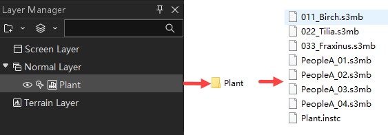
- Add Vegetation: After selecting a specific vegetation asset in the vegetation list, you can set relevant parameters in the asset editing panel on the right side of the software and add vegetation to the scene. After adding, an instanced layer with the specified name will be added in the Layer Manager.
- Layer: Sets the name of the instanced layer where the vegetation asset is located. Default is Plant.
- Group Name: Sets the name of the group where the vegetation asset is located. Default is Group1.
- Add Mode: Sets the mode for adding vegetation assets in the scene, including Area Add, Along Line Add, and Single Add.
- Draw: After selecting the add mode and setting the corresponding parameters, click the Draw button, move the mouse to the scene to draw the placement path of vegetation assets.
- When Area Add is selected, left-click to start drawing a polygon area, right-click to finish drawing.
- When Along Line Add is selected, left-click to start drawing a line, right-click to finish drawing.
- When Single Add is selected, left-click at the specified position in the scene, right-click to finish drawing.
- Spacing: Sets the spacing between two vegetation assets. Default is 15, in meters.
- Random Size: Check the checkbox before random size, then set the scaling ratio range for vegetation assets (default is 1~5). Vegetation assets will be scaled randomly within this range. If unchecked, enter the vegetation asset scaling ratio in the first text box, and the vegetation assets will be drawn at the specified ratio.
- Random Angle: Check the checkbox before random angle. When drawing, vegetation assets will rotate randomly around the Z-axis. If unchecked, vegetation assets will be drawn at a fixed angle.

- Edit Vegetation: After selecting the vegetation asset to edit in the scene, you can view and set parameters such as translation, rotation angle, and scale ratio in the asset editing panel on the right side of the software.
- Translation: Enter the translation distance along the X/Y/Z axis in the X/Y/Z text boxes, in meters.
- Rotation Angle: Enter the counterclockwise rotation angle around the X/Y/Z axis in the X/Y/Z text boxes, in degrees.
- Scale Ratio: Enter the scaling ratio along the X/Y/Z axis in the X/Y/Z text boxes, in multiples.
- After setting, click the Apply button to adjust the asset effect according to the specified parameters.
-
Save Beautification Result: After setting, click the Save Beautification Result button in the Scene Beautification tab. The instanced layer and corresponding vegetation assets will be saved in a folder with the specified asset name under the specified project path.
Add Static Model
- Open a scene or create a new scene, click the Scene Beautification button in the Scene Beautification group under the Scene tab. The "Asset Manager" dialog box will appear at the bottom of the current window. Select "Static Model" in the dialog box to display the built-in static model assets.
- The Asset Manager includes the toolbar, vegetation list, etc.
- Toolbar: Provides back, refresh, and search functions.
- Back: Allows returning from the current list to the parent menu.
- Refresh: Refreshes the content in the current static model list.
- Search: Enter an asset name in the text box at the upper right of the specific list to display only relevant assets in the current list.
- Static Model List (Library): Displays built-in assets such as characters, urban plot accessories, sports facilities, road accessories, etc.
- Right-click a specific static model to open its containing folder.
- Open Containing Folder: Locates the folder where the currently selected asset is located.
- Right-click a blank area in the model asset list to open the folder.
- Open Folder: Opens the folder where the current asset library is located.
- The right-click menu of the static model asset library (e.g., characters, urban plot accessories) provides open containing folder, rename, and delete folder functions.
- Open Containing Folder: Locates the folder where the current asset library is located.
- Rename: Sets a new name for the currently selected model asset library.
- Delete Folder: Deletes the folder corresponding to the currently selected model asset library.
- The right-click menu of a blank area in the static model asset library list provides new folder and open containing folder operations.
- New Folder: Creates a new static model asset folder in the current list.
- Open Containing Folder: Locates the parent folder containing all current list items.
- Toolbar: Provides back, refresh, and search functions.
- Add Static Model: After selecting a specific asset in the static model asset list, you can set relevant parameters in the asset editing panel on the right side of the software and add static models to the scene. After adding, an instanced layer with the specified name will be added in the Layer Manager.
- Layer: Sets the name of the instanced layer where the asset is located.
- Group Name: Sets the name of the group where the asset is located. Default is Group1.
- Add Mode: Sets the mode for adding assets in the scene, including Along Line Add and Single Add.
- Draw: After selecting the add mode and setting the corresponding parameters, click the Draw button, move the mouse to the scene to draw the placement path of assets.
- When Along Line Add is selected, left-click to start drawing a line, right-click to finish drawing.
- When Single Add is selected, left-click at the specified position in the scene to complete drawing.
- Spaced Array: When Along Line Add is selected, check Spaced Array to place model objects at specified intervals along the path.
- Spacing: Sets the interval distance between static model objects, in meters. Default is 20.0.
- Continuous Array: When Along Line Add is selected, check Continuous Array to arrange model objects continuously along the specified path.
- Smoothness Factor: Sets the smoothness of object distribution along the path, ranging from 1 to 5. Increasing this value increases the number of interpolation points, making the trajectory smoother but also increasing computation time. For performance reasons, it is recommended to keep this value no higher than 3.
- Translation: Enter the translation distance along the X/Y/Z axis in the X/Y/Z text boxes, in meters.
- Rotation Angle: Enter the counterclockwise rotation angle around the X/Y/Z axis in the X/Y/Z text boxes, in degrees.
- Scale Ratio: Enter the scaling ratio along the X/Y/Z axis in the X/Y/Z text boxes, in multiples.
- Edit Static Model: After selecting the static model to edit in the scene, you can view and set parameters such as translation, rotation angle, and scale ratio in the asset editing panel on the right side of the software. After setting, click the Apply button to adjust the asset effect according to the specified parameters.
-
Save Beautification Result: After setting, click the Save Beautification Result button in the Scene Beautification tab. The instanced layer and corresponding static model assets will be saved in a folder with the specified asset name under the specified project path.
