


Common infrastructure in the real world, such as municipal water networks, power lines, natural gas pipelines, telecommunication networks, and river systems, can all be modeled and analyzed through facility networks, as they inherently represent directional resource flow structures.
Facility network analysis is one of the network analysis functionalities, primarily used for connectivity analysis and trace analysis.
Facility network analysis requires establishing a network model with specific rules, and the facility network must have flow direction. This is its unique feature. Flow direction refers to the path of resource movement, determined by network topology, source, and sink locations.
Basic Concepts
A facility network essentially consists of edges and junctions, modeling real-world infrastructure through connectivity rules. Users define how resources flow within the network by specifying the roles and rules of its fundamental elements (point and line objects).
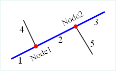 |
| Figure 1: Schematic diagram of a facility network |
Figure 1 shows a simple facility network. The blue bold lines (1, 2, 3) represent main pipelines, while the thin black lines (4, 5) are branch pipelines. The red junctions Node1 and Node2 connect main and branch pipelines.
Note: The current CommonGIS kernel does not support complex edges; all such edges are physically split into simple edges.
- Edges: Lines in the facility network model representing resource channels, such as water pipes, power lines, or gas pipelines.
- Simple Edges: Edges that connect only two junctions at their endpoints. For example, branch pipelines (4 and 5 in Figure 1) connect to main pipelines at one end and secondary pipelines at the other. Simple edges lack internal connectivity; adding a junction requires physically splitting them.
- Complex Edges: Edges that allow adding junctions along their length without physical splitting. The blue main pipelines in Figure 1 demonstrate this, connecting to branch pipelines via Node1 and Node2 without being split.
- Junctions: Points in the facility network model representing intersections of multiple edges, such as pump stations, valves, or user access points.
- Source: A junction where resources originate (e.g., power plants or water stations).
- Sink: A junction where resources terminate (e.g., user access points in water or power networks).
- Network Weight: A parameter associated with network elements. For example, a water pressure weight linked to pipe length could represent pressure loss due to friction. Weights may correlate with object fields or remain zero (e.g., isolated junctions).
- Enabled/Disabled Elements: Edges or junctions can be disabled (e.g., closed valves blocking water flow). A specific field typically indicates this status.
Values in the flow direction field have specific meanings:
| Value | Meaning |
| 0 | Flow direction from FromNode to ToNode. |
| 1 | Flow direction from ToNode to FromNode. |
| 2 | Undetermined flow (e.g., loops or ambiguous cases). |
| 3 | Disconnected edge. |
The illustration below shows flow directions in a river network. Colors and line styles represent different flow states, with numeric meanings explained in the table above.
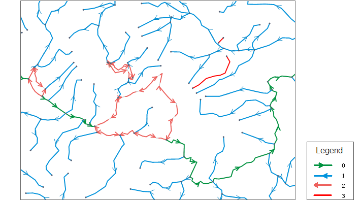 |
| Figure: Flow direction visualization |