


Transportation analysis brings convenience to businesses, public services, and daily life. Analyst results provide effective implementation plans to help users make more rational decisions. Transportation analysis can help solve the following practical problems:
- What is the shortest route from point A to point B?
- When visiting tourist attractions, how to select a route that covers as many attractions as possible in one trip?
- What is the customer coverage area of a newly opened supermarket, and how should the inventory be determined?
- How to dispatch the nearest fire engine for rescue after a fire occurs?
- How can a delivery courier in Dongcheng District complete all express tasks in the shortest time?
In the geospatial world, public infrastructure (power facilities, telecommunication and cable networks, road traffic, water networks, etc.) is abstracted as "network systems". A network system refers to a mesh system composed of interconnected segments, where the network model is an abstract representation of real-world network systems. For example, in urban transportation networks, polylines like roads are abstracted as edges (network arcs), while point features like intersections and bus stops are abstracted as nodes. In network models, resources and information can travel along arcs from one node to another. Essentially, a network consists of edges (lines) and junctions (nodes), representing potential paths between locations.
Basic Concepts
Network is a model composed of interrelated arcs, nodes, and their attributes. Networks are used to represent real-world elements like roads and pipelines.
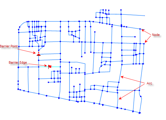 |
| Figure: Network schematic |
As shown above, a network not only has abstract topology between arcs and nodes but also possesses GIS spatial data characteristics, including geometric positioning and geographic attributes (topology describes spatial relationships between geographic objects, such as connections between nodes and lines, or lines and polygons).
Below are key concepts in network models:
A node is where network arcs connect, as illustrated above. Nodes can represent real-world features like road intersections or river confluences. Both nodes and arcs have attribute tables, with adjacency relationships linked through table fields.
An edge (arc) is a segment in the network connected to other arcs through nodes. Edges can represent highways, railways, power lines, or rivers. Interconnected edges form topological relationships.
In real-world scenarios, traveling from a starting point to a destination through roads and intersections incurs costs measurable by distance, time, or currency. In network models, these costs are abstracted as network resistance and stored in property fields called resistance fields.
A center is a discrete facility located at a node that can receive or provide resources. Facilities refer to materials, resources, information, and cultural environments required by GIS. For example, schools possess educational resources requiring physical attendance, while retail warehouses store goods for daily distribution. Centers are essentially network nodes.
Urban traffic congestion is random and dynamic. To reflect real-time network conditions, blocked arcs can be temporarily forbidden from passage, resuming normal status when traffic clears. The concept of barrier edges/points solves this by maintaining independence from existing network parameters.
A turn is the process of moving from one arc through a node to an adjacent arc. Turn cost refers to the expense required to complete the turn. A turn table stores these costs, listing all possible turns at intersections with four fields: FromEdgeID (start edge), ToEdgeID (end edge), NodeID, and TurnCost. Each record represents a turning method and its associated cost. Turn costs are typically directional, with negative values indicating prohibited turns.
For example, during network analysis of roads, we often encounter intersections. The left figure below shows a crossroad schematic, while the right table displays its corresponding turn table with vehicle turning directions and associated costs.
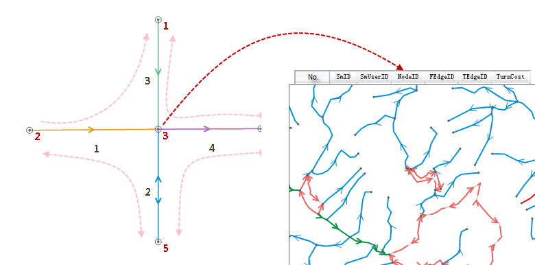 |
| Figure: Turn table schematic |
- Node
- Edge
- Network resistance
- Center
- Barrier edges and barrier points
- Turn Table